GENE SLOVERS
US NAVY PAGES
OP-1063 January 1944
The Stable Element
Mark 6 and Mods
These files require the free Adobe reader or browser add in to view. If you cannot open these files, you can download and install the free reader. Be sure to select the version for your operating system. (Windows Vista, XP, Mac, Linux, etc.)
Get free Adobe Reader if you can't open files
These files are searchable from within your reader.
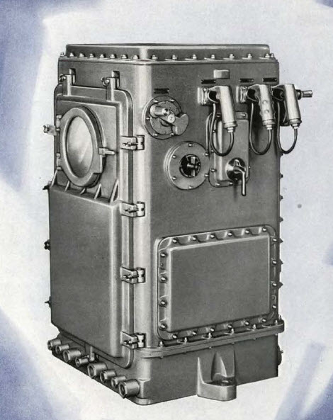
The Stable Element is located adjacent to the Computer in the Plotting Room and performs two major functions:
1. It measures Level and Cross Level angles caused by variation of the position of the deck of the ship with respect to the horizontal, and utilizes these angles in such a manner as to keep the lines of sight of the telescope and the rangefinder positioned automatically on the target while the ship pitches and rolls.
2. It provides means for firing the guns.
Ordnance Pamphlet No. 1063 describes the theory, care, and operation of the Stable Element Mark 6 and Mods. Data on the associated Control Panels Marks 7 and 8 are included. Although Ordnance Pamphlet No. 1063 was written primarily for the Stable Element Mark 6 and Mods., occasional notes have been added to indicate wherein the Stable Element Mark 5 differs from the Stable Element Mark 6.
The first major function listed above is the basic duty of the Stable Element.
The method by which the instrument performs this function is described in detail
in the section on Application, but it may be briefly stated here that a gyroscope
is the heart of the instrument, the gyroscope providing a horizontal reference
plane about which Level and Cross Level Angles are measured as the ship
pitches and rolls. The construction is such that any motion of the ship's deck
with respect to this plane causes relative motion between the gyro and the
gimbals in which it is mounted.
Any motion or angular displacement due to these causes is measured by maintaining
a pair of follow-up coils, which are mounted on one of the gimbals, in
alignment with a magnet mounted on the gyro case. This is accomplished by an
electronically actuated motor-driven follow-up mechanism. As the follow-up
mechanism acts to keep the follow-up coils aligned with the magnet, the angle
generated by each gimbal is indicated about its corresponding (Level or Cross
Level) axis on dials calibrated in minutes of arc.
In addition, the angle generated by each gimbal is also applied to Synchro generators and to mechanical output shafts for transmission to other instruments or elements to be controlled.
FIRING THE GUNS
The instrument also provides means for automatically firing the guns. The guns
may also be fired by means of the firing keys on the front of the housing. Settings
are possible for:
1. Continuous Fire
2. Automatic Firing in Selected Level
3. Automatic Firing in Selected Cross Level
4. Hand Firing in Level
5. Hand Firing in Cross Level
The Table of Contents is hyper-linked for each section. Just click on the section you want.
This file is also indexed and searchable. Enter the phrase you want in your reader's search block. If that does not work, try a different phrase. OCR isn't perfect.
OP1063 The Stable Element 33.4 mb
Related material: Computer Mark 48 Mod 1