US NAVY PAGES
NAVAL ORDNANCE AND GUNNERY
CHAPTER XVI
THE NAVAL LANDING GUN
The gun consists of a built-up, forged-steel barrel, with one hydraulic recoil cylinder located above the barrel, and one hydropneumatic counter-recoil cylinder located beneath the barrel.
The vertical sliding wedge breech mechanism slides in a mortise cut in the gun-breech housing. Motion is imparted to the breech block by an operating handle and lever. The breech block is returned automatically to the closed position by means of an operating spring which is connected to the operating shaft.
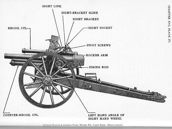
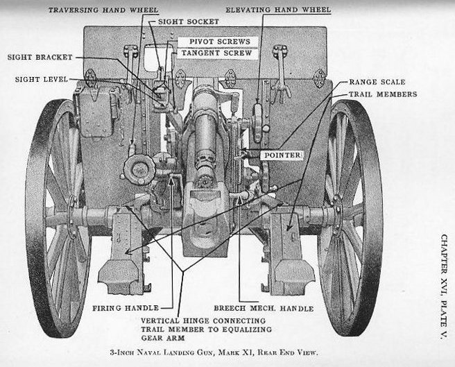
1602. The mount.- In the following description of the mounting of the landing gun, the parts corresponding to the stand, carriage, and slide of the usual broadside mount are respectively known as the pintle bearing, top carriage, and cradle (see Plate I).
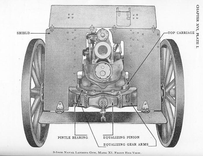
The trail is of the split type and is built up of steel plate. At its front end each member is attached to an equalizing gear by a vertical hinge upon the carriage axle (see Plate I).
The equalizing gear, which permits each member of the trail to be moved independently, and thereby placed at different levels on uneven ground, distributes the firing forces to each trail member. At the rear ends of the trail members are the spades, which may be imbedded in the ground to prevent movement of the carriage to the rear on recoil. The trail handles and the eye for securing the drag-rope snap hook are riveted to the trail near its rear end.
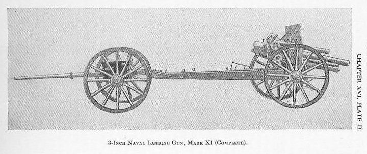
The carriage is provided with two wheels, which support the gun and on which it is moved from place to place. A tool chest and two ammunition boxes, each containing 20 rounds, are carried on a separate limber (Plate II).
I SPLIT THE PICTURE INTO 2 PIECES IN HOPES THAT YOU CAN READ THE SMALL PRINT.
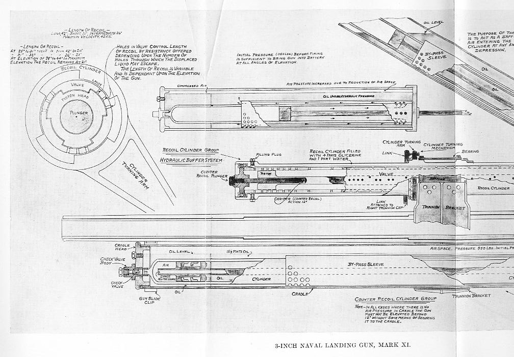
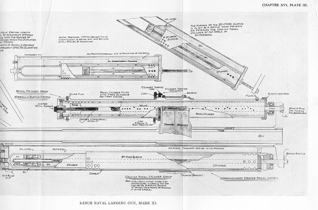
On recoil the piston displaces the liquid from rear to front through the holes in the recoil valve. The absorption of the energy of recoil by the resistance of displacing the liquid brings the gun to rest. The feature of this recoil system that the length of recoil is made variable by varying the number of holes through which the displaced liquid may pass. As the elevation of the gun is changed, a spring connecting linkage to the top carriage causes the recoil cylinder to rotate about the recoil valve; the lands of the cylinder hence gradually close or open more of the holes in the valve, and the increase or the decrease in resistance decreases or increases the length of recoil respectively. When the gun is fired in the horizontal position, or nearly so, the length of recoil is about 14 calibers; but to prevent the breech from striking the ground at higher angles of fire, the recoil is decreased approximately to 7 or 5 calibers.
The piston rod is hollow-bored for about one-third of its length from the front face of the piston to form a chamber for the counter recoil plunger. This chamber is known as the dashpot; it prevents the gun from returning to battery violently.
1604. The counter—recoil system (Plate III). The counter-recoil group consists principally of the cradle cylinder, the by-pass sleeve, the counter-recoil cylinder, and the piston and piston rod. The lower part of the cradle is a bored cylinder, into the rear end of which the by-pass sleeve is screwed. The sleeve extends about two thirds the length of the cradle cylinder; at its forward lower end a number of holes are drilled. Into the rear end of the by-pass sleeve is screwed the counter-recoil cylinder, near the rear end of which are twelve holes evenly spaced in sets of three. The counter-recoil piston is assembled on its piston rod, which passes through the counter-recoil cylinder packing gland to the gun yoke. The recoil liquid fills the cradle cylinder partly and the space in rear of the piston in the counter-recoil cylinder. The remaining volume within the cradle cylinder is filled with air at an initial pressure of about 350 pounds per square inch.
During recoil the counter-recoil piston displaces a quantity of liquid from the counter-recoil cylinder through the holes near its rear end into the cradle cylinder. The volume of air in the cradle cylinder is thus put under an increasing air pressure, the energy of which returns the gun to battery after the recoil has been checked. The purpose of the by-pass sleeve is to form a baffle, which prevents the entrance of air into the counter-recoil cylinder when the gun is depressed.
By rotating either the right or left angle of site (position) handwheel the rocker is rotated about the rocker trunnions, the mechanism from the handwheel terminating in a bevel gear and the angle of site worm geared to the angle of site rocker. As the elevating arc of the cradle rests in a bracket secured to the rocker, movement of the rocker moves the gun in a similar direction. The sight, which is rigidly connected to the left rocker arm, also moves.
To elevate or depress the gun to a required angle of elevation, the elevating handwheel is rotated. The mechanism from the handwheel terminates at a bevel gear and elevating worm, which engages the elevating arc of the cradle. This part of the elevating system is carried entirely by the rocker. Movement of the elevating handwheel causes the cradle and gun to move independently of the rocker and, hence, of the sight.
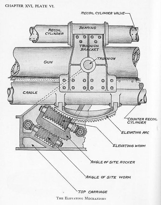
To elevate or depress the gun to a required angle of elevation, the elevating handwheel is rotated. The mechanism from the handwheel terminates at a bevel gear and elevating worm, which engages the elevating arc of the cradle. This part of the elevating system is carried entirely by the rocker. Movement of the elevating handwheel causes the cradle and gun to move independently of the rocker and, hence, of the sight.
1606. Design principle of sights-As field guns often have to be set up on uneven ground where the guns have considerable trunnion tilt and also where all guns in the battery will have different amounts of trunnion tilt, it is especially desirable that the sights on these guns correct for trunnion tilt.
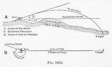
(1) The term angle of site, which is synonymous with angle of position, is employed by artillerists ashore.
The sights for the 3-inch, Mark XI, landing gun are designed to operate on this principle. The sight does not rotate about the axis of the gun but about the sight-bracket slide pin, which, by means of a parallel motion mechanism connected to the gun trunnion, always is maintained parallel to the axis of the bore of the gun. The fulcrum block is mounted on the sight-bracket slide pin, and the sight socket which holds the sight (peep or panoramic) is mounted on the fulcrum block by means of two pivot screws. The axes of these two pivot screws are in line with each other but at right angles to the axis of the sight-bracket slide pin. The sight socket is set in the vertical position by means of a level mounted on the rear side and a tangent screw at the bottom.
1607. Effect of trunnion tilt.-An examination of the sight on a broadside gun will show that it has been designed so that the line of sight can be set at the prescribed angle with the axis of the gun in the vertical plane and at the prescribed angle with the axis of the gun in the horizontal plane. This holds true only so long as the axis of the trunnions remains in the horizontal plane, as it is apparent that, if the gun with its sight is rotated about the axis of the gun through 90°, then any angle of sight elevation set on the sights will become, in effect, an angle of sight deflection, and any angle of sight deflection set on the sights will become, in effect, an angle of sight elevation.
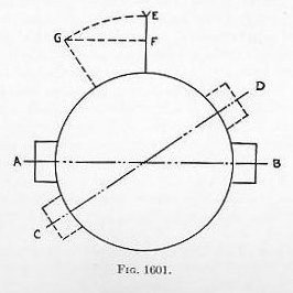
If the gun is fired with the trunnions tilted and the sights set as shown it is evident that the shot will fall short of and to the left of the target.
From a study of Fig. 1601, it is apparent that trunnion tilt would introduce no errors in gun sights if means could be provided for keeping sight points at all times in the vertical plane by rotating the sight arm about an axis that always remains parallel to the axis of the gun. If both the front sight point and the rear sight point were mounted on a cylinder that encircled the gun and this cylinder, regardless of the amount of trunnion tilt, could be so positioned that the sight points would always remain vertical, then trunnion tilt would in no way affect the accuracy of the sights.
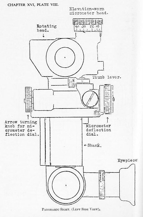
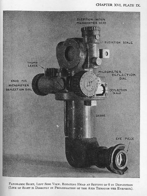
1608. The panoramic sight telescope (Plates VII, VIII, IX, X).-For protection, field batteries usually are placed out of view of the enemy. Thus, a sight must be employed which is capable of being used for either direct or indirect fire. The panoramic sight fulfills these conditions.
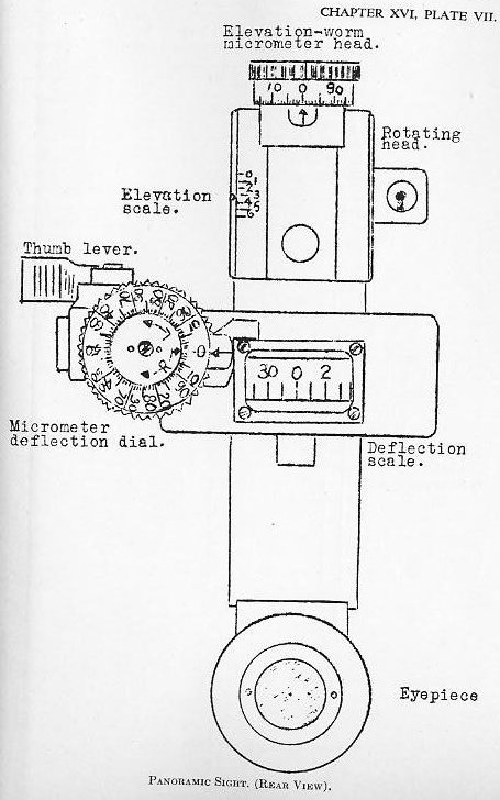
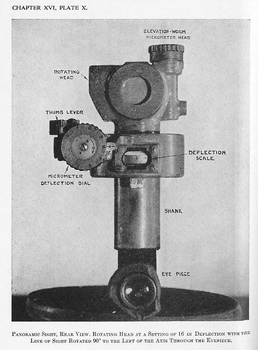
Upon the rear face of the rotating head is a small scale graduated in hundreds of mils up to 600 mils. On top of the rotating head is the elevation-worm micrometer head, the scale on its periphery being divided into 100 equal divisions, each corresponding to 1 mil. Thus, one complete revolution of the micrometer head-is equal to the distance between adjacent graduations upon the scale on the rear face of the rotating head. When the index pointer of the latter scale is at 300 mils and the micrometer scale at 0, then the line of sight is perpendicular to the vertical axis of the telescope.
The deflection scale shows through a small glass window on the shank below the rotating head. It is graduated into 64 equal divisions about its periphery from 0 to 32 right and from 32 to 0 left. The deflection micrometer dial is on the left of the shank and is divided into 100 equal divisions each corresponding to 1 mil or 1/6400 of a circle.
(2) The mil here referred to is the arbitrary Army mil, which is an angle of a size such that 6,400 mils = 360°. See footnote p. 157, Exterior Ballistics, 1935.
One complete revolution of the arrow pointer within the micrometer deflection dial then is equal to the distance between adjacent graduations on the deflection scale on the shank. When the deflection scale and the deflection dial are at zero, the line of sight is parallel to a vertical plane through the axis of the bore of the gun. At 16 (or 1,600 mils), the line of sight is pointing directly to the right or directly to the left; at 32 the line of sight is pointing directly to the rear. The micrometer deflection dial is marked from 0 to 100 right in black and from 0 to 100 left in red to facilitate sight setting.
The micrometer deflection dial may be rotated independently of the arrow indicator. Thus, with a deflection already set on the scale, to increase or decrease it by a certain number of mils, the micrometer deflection dial may be turned till the zero mark is in line with the arrow on the central spindle, and then the arrow turned the required number of mils right or left. A small thumb lever above the dial, when pushed in, throws the dial arrow spindle out of gear with the deflection scale on the shank. If the change to be made is large, the pointer presses in this level with his left thumb, grasps the rotating head with his right hand and turns it quickly to the new deflection setting.
A cross level, mounted below the eyepiece, provides the means for insuring that a plane through the axis of the shank and eyepiece is parallel to a vertical plane through the axis of the bore under various conditions of elevation and unevenness of ground. A parallel motion mechanism attached to the panoramic-sight mount keeps the latter in a fixed position with relation to the axis of the gun when the gun is elevated and depressed by means of the elevation handwheel. When the angle of site handwheel is used, however, the rocker is rotated, carrying both gun and sight.
1609. The peep sight has a deflection scale graduated in tens of mils and a micrometer wheel divided into 20 equal divisions so that each division corresponds to one-half of a mil. No means is provided for elevating and depressing the line of sight independent of the angle of site mechanism, as provided in the elevation device of the panoramic sight. The peep sight is used for direct fire only, while the panoramic sight is used for either direct or indirect fire.
1610. Operation, direct fire. Aboard ship the sight of a gun is depressed below the axis of the gun by the amount of the necessary angle of elevation, and the gun and sight are then elevated together until the line of sight is laid on the target. Due to the roll and pitch of the ship the pointing and training of the gun is continual. However, ashore with field guns, where there is no movement of the gun platform, the procedure is reversed. The line of sight is first laid upon the target, and then the gun is elevated above the line of sight by the amount of the angle of elevation.
The gun pointer standing at the left of the gun and in rear of the panoramic sight:
(a) Sets the panoramic line of sight perpendicular to the vertical axis of the telescope. The scale is set at 3 and the micrometer head at 0, namely, at 300 mils elevation, the corresponding vertical zero position of the telescope.
(c) Sets the deflection scale to the deflection ordered.
(d) Brings the intersection of his telescopic cross wires on the target by means of the angle of site (position) handwheel and the training (traversing) handwheel.
The plugman, standing to the right of the gun:
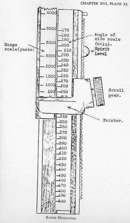
(e) Sets the pointer (Plate V) by the scroll gear to 300, corresponding to the zero angle of position, on the angle of site (position) scale. As in pointer fire in naval gunnery, in direct fire the angle of position is eliminated as an element of the fire control problem.
(f) Elevates the gun, by means of the elevating handwheel, to the gun range ordered, by bringing the range on the range scale (Plate V) in line with the pointer.
If the gun and sight are properly boresighted and the range scale ( Plate V) is set for zero range (as shown on Plate V), the operation of the angle of sight handwheel, as explained in (d) above, which moves the rocker carrying both the gun and sight, will bring both the line of sight of the telescope and the axis of the bore of the gun to a plane passing through the target. Then, when the elevation handwheel is moved, as in (f) above, the gun and its cradle are elevated within the rocker, but the rocker and its attached sight remain stationary, the line of sight remaining on the target.
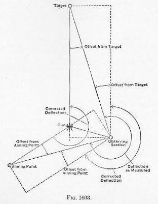
1611. Operation, indirect fire.-In this method of fire the battery commander measures the deflection of the aiming point from the target and the angle of site (position) of the target above or below the horizontal plane of the gun, both in mils. (Figure 1602.) An assistant measures the range in yards. The deflection determined above is corrected for the ballistic correction, namely, the errors due to drift, wind, and motion of the target across the line of fire.
The pointer:
(a) Sets the deflection scale of the panoramic sight to the reading ordered by the battery commander.
(c) Trains the gun in azimuth with the training (traversing) hand-wheel until his cross wires are on the point of aim. If the point of aim is above or below the horizontal, the telescopic line of sight is raised or lowered as necessary by means of the elevation micrometer head.
The plugman:
(d) Centers the fore and aft bubble of the right rocker arm by elevating or depressing the rocker with the angle of site handwheel, thus placing the axis of the gun in the horizontal plane, provided that the range scale is set for zero range and the angle of site (position) is set for a zero angle of position (300 mils) (Plate V).
(e) Sets the pointer by the scroll gear knob (Plate V) to the angle of site (position), as determined and ordered by the battery commander.
For instance, if the target is 10 mils higher than the gun, the pointer is set to 310; if 10 mils lower, to 290. This movement of the pointer is merely a rule for adding or subtracting the angle of site (position) to the angle of elevation for the run range.
(f) Elevates the gun, employing the elevation handwheel, until the gun range on the range scale (Plate V) is in line with the pointer.
The elevation handwheel elevates only the cradle and the gun within the rocker, and thence the position of the rocker arm, which is set by the position of the fore-and-aft bubble, as explained in (d), is not changed.
1612. Battery commander’s telescope. This is an instrument for measuring horizontal and vertical angles in mils and is essentially a specially adapted panoramic sight mounted on a tripod.
Battery commander’s ruler.- This is a slide ruler 6.7 inches long by 1 inch wide with a cord about 24 inches long made fast to its center. When one end of the cord is attached to the top button of the coat and the ruler held horizontally or vertically and at the same time at right angles to the taut cord, at a distance of 20 inches from the eye, the scale on the edge of the ruler measures in mils the visual angle subtended by the corresponding portion of the ruler. The cord may be adjusted to proper length by checking with the battery commander’s telescope or panoramic sight.
1613. Sextant telemeter.-This is an angle-measuring instrument. By means of scales provided, it may be used for determination of distances and measurement of angles of deflection and site.
The offset from the aiming point is the perpendicular distance from the observing station to the gun aiming-point line or line prolonged, reduced to mils by dividing it by 1/1000 of the distance to the aiming point.
The offset from the target is the perpendicular distance from the observing station to the gun target line or line prolonged, reduced to mils by dividing it by 1/1000 of the distance to the target.
These corrections are sometimes added to the measured deflection, and sometimes subtracted, depending on the relative positions of observing station and aiming point with reference to the gun and target.