| NAVAL ORDNANCE AND GUNNERY CHAPTER 12 TORPEDOES |
| F. Control Systems of a Mark 15 Torpedo 12F1. General The torpedo is provided with 2 pairs of rudders-1 horizontal and 1 vertical. The vertical rudders control the steering of the torpedo to left or right, and keep it on its preset course. The horizontal rudders steer the torpedo up or down, to keep it at its preset depth. The 2 control systems-1 for steering and 1 for depth-are located in the afterbody. The steering system consists of a gyro, a pallet mechanism, and a steering engine. The depth system consists of a diaphragm, pendulum, and depth engine. Each of the two engines operates a rod that extends aft through a packing in the after bulkhead of the afterbody. Each of the two rods is connected to its pair of rudders through a semicircular yoke. 12F2. Functional description The control mechanisms have been called the “brains” of the torpedo. The steering mechanism turns the torpedo to its preset course, and keeps it there. If the torpedo wanders off course to left or right, the steering mechanism throws the vertical steering rudders to correct the error. And the depth mechanism brings the torpedo to its preset depth and keeps it there. If it starts to rise too high in the water, or sink too low, the depth mechanism throws the horizontal rudders to bring the torpedo back to its proper depth. Each of the 2 control mechanisms consists of 3 parts: a sensing part, a detecting part, and an engine. Sensing part. In the steering mechanism, the sensing part is the gyroscope. There is no way to keep the torpedo on course unless some part of the mechanism always points in the same direction-regardless of which way the torpedo may turn. Throughout the torpedo run, the axis of the gyro always points in the same direction. The depth mechanism has two sensing parts-a diaphragm and a pendulum. To keep the torpedo at the proper depth the mechanism must include a part that can measure how deep the torpedo is in the water. The diaphragm does that job. The pendulum is sensitive to the “running attitude” of the torpedo. Since the pendulum tends to hang straight down, it can tell if the torpedo is tilted up or down, or if it is running level. Detecting part. In the steering mechanism, the detecting part is the pallet mechanism. Assume that a torpedo has been fired with zero gyro angle. Then the axis of the gyro lies along the desired course of the torpedo, and it will point out the proper course throughout the run. If the torpedo turns to the left or right from its course, the pallet mechanism will detect the difference and send correcting orders to the steering engine. In the depth mechanism, the diaphragm and pendulum are linked together. Through this linkage they work together to send corrective signals to the depth engine. Engines. The steering engine, when it gets an order from the pallet mechanism, throws the vertical steering rudders in the direction required to bring the torpedo back on course. When the depth engine gets an order from the diaphragm and pendulum linkage, it moves the horizontal depth rudders in the direction required to bring the torpedo back to its preset depth. Both engines are powered by working-pressure air. The two control mechanisms provide only enough energy to actuate the controls of the engines. Compressed air, rather than the gyro or diaphragm and pendulum, does the work of turning the rudders. |
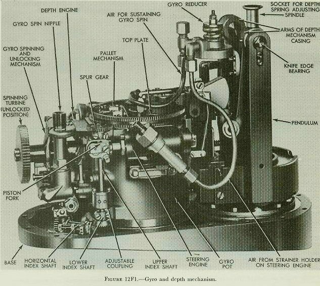 |
| 12F3. Control mechanism assembly Figure 12F1 shows the control mechanism assembly of a Mark 15 torpedo, looking from the starboard side. The entire assembly is mounted on an oval base plate, which fits a flanged opening in the lower side of the afterbody shell, and is secured in place by screws. The vertical cylinder in the center of the assembly is the gyro pot, which serves as a housing for the gyro and its gimbal mounting. The pallet mechanism, which detects the relative position of the gyro axis, is mounted on the top plate at the top of the gyro pot. For an angle shot, the top plate and pallet mechanism are rotated, through a shaft and gear train, by a setting socket on the outside of the afterbody shell. The pallet mechanism is linked to the valve of the steering engine, which is visible in figure 12F1 on the starboard side of the gyro pot. The depth engine is mounted in a similar position on the opposite side of the pot. The air strainer body is mounted on the outboard side of the steering engine. Air passes from the strainer to the steering and depth engines, and to the gyro reducer (near the upper right in figure 12F1). Low-pressure air for sustaining the gyro spin enters the gyro pot through a fitting in the center of the top plate. The gyro spinning and unlocking mechanism gives the gyro its initial speed at the moment of firing. It is visible at the extreme left in figure 12F1. The pendulum of the depth mechanism is at the extreme right. The diaphragm assembly is mounted on the base plate under the pendulum. |
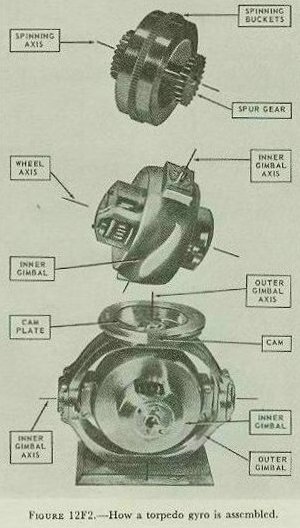 |
| 12F4. Gyro The action of a gyroscope is explained elsewhere in this text. The gyro has two properties that make it useful in ordnance devices. The property of precession is used in the lead-computing sight. The property of rigidity in space is used in the torpedo. Throughout the torpedo run, the axis of the spinning gyro remains rigid in space; that is, it points constantly in the same direction. If the torpedo turns off its proper course, it must turn with respect to the gyro axis, which remains fixed. The pallet mechanism detects this relative turning, and sends the necessary corrective orders to the steering engine. Figure 12F2 shows how a torpedo gyro is assembled in its gimbals. The gyro wheel alone is shown at the top of the illustration. Most of its weight is concentrated in its outer rim, to increase its gyroscopic action. Throughout the torpedo run, low-pressure air from the gyro reducer strikes the spinning buckets on the outer rim of the wheel, to maintain the original rate of spin. A spur gear is mounted on each end of the gyro wheel axis. One of these is engaged by a gear of the gyro spinning and unlocking mechanism, to give the wheel its initial spin. The other is present to balance the first, and to provide equal air resistance so that no unbalanced forces will be applied to the gyro. The middle picture shows the gyro wheel mounted in its inner gimbal. The wheel is free to rotate on its bearings within the inner gimbal. Note that parts of the inner gimbal are cut away to expose the two spur gears. The lower picture shows the gyro and gimbals completely assembled. (Note that in each of the three pictures the gyro wheel is shown in a different position.) In the torpedo, the gyro spins on a fore-and-aft horizontal axis within the inner gimbal. The inner gimbal itself is free to rotate on a horizontal axis at right angles to that of the gyro wheel, on bearings in the outer gimbal. The outer gimbal is free to rotate on a vertical axis, in bearings mounted in the top and bottom plates of the gyro pot. Thus the gyro wheel, with three degrees of freedom, is free to turn in any direction with respect to the torpedo. Or, more precisely, the torpedo is free to turn in any direction without disturbing the gyro axis. |
| The cam plate is rigidly attached to the top of the outer gimbal. If the torpedo turns with respect to the gyro, it therefore turns with respect to the cam plate. The pallet mechanism, by detecting the relative position of the cam on the cam plate, is able to determine when the torpedo has turned off course, and in which direction. The gyro sustaining air enters through a fitting in the center of the top plate. It flows through passages in the upper arms of the outer gimbal, through the inner gimbal bearings, and through passages in the inner gimbal arms to the spinning buckets. 12F5. Spinning and unlocking mechanism At the instant of firing, the gyro is rigidly locked with its axis of spin parallel to the axis of the torpedo. This is accomplished by the centering pin of the spin-fling and unlocking mechanism. The centering pin is engaged in a cavity in the center of the after side of the inner gimbal. This cavity may be seen in the lower illustration in figure 12F2; it is located just below the opening for the spur gear. The spur gear is engaged by a gear on the spinning mechanism. When the starting valve opens, flask-pressure air enters the spinning mechanism and spins its turbine. This spin is transmitted to the gyro wheel through its spur gear. The gyro wheel reaches full speed in a little more than half a second. The spinning gear then snaps out of engagement with the gyro spur gear. When this action is completed, the centering pin snaps out of the cavity, unlocking the gyro and leaving it free to control the steering of the torpedo. A valve in the spinning and unlocking mechanism closes automatically, to shut off the supply of high-pressure air. |
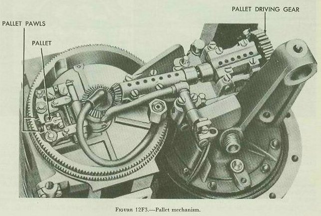 |
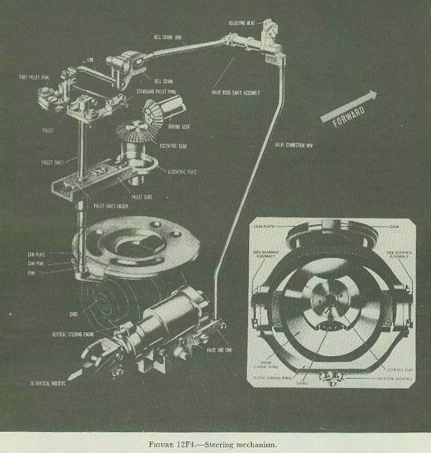
| 12F6. Pallet mechanism Figure 12F3 shows the pallet mechanism of a Mark 15 torpedo, mounted on the gyro top plate. The pallet driving gear is turned by a spur gear on the forward (outer) propeller shaft. Its rotation is transmitted to the bevel gear in the center of the gyro top plate. Figure 12F4 is a diagram of the whole steering mechanism. (The mechanism shown is actually that of a Mark 13 torpedo. It differs from the Mark 15 in a few details of the linkage between the pallet mechanism and the steering engine. This difference may be seen by comparing figure 12F4 with 12F3. The pallet mechanisms, and the principles of operation, are the same.) On the shaft of the eccentric gear (figure 12F4) is a cam that passes through an opening in the eccentric plate. Rotation of the cam gives a fore-and-aft motion to the plate, and to the pallet shaft holder attached to it. The pallet shaft is free to turn within its holder, but must move fore-and-aft with it. Thus the pallet shaft and its pallet (at the top) and its two cam pawls (at the bottom) have a continual fore-and-aft motion throughout the torpedo run. If the pallet (figure 12F4) is on dead center during its motion aft, it will pass between the two pallet pawls. But if the pallet shaft has been rotated in either direction, the pallet will strike one of the pallet pawls and throw it aft. The two pawls are so linked that when one of them is thrown aft, the other is automatically thrown forward. At the same time, the linkage will move the valve of the steering engine in or out. Note the cam on the after edge of the cam plate. Because the cam plate is rigidly attached to the outer gimbal, the position of the cam indicates the desired course of the torpedo. On the starboard side of the cam, a groove is cut in the lower edge of the cam plate; on the port side, a similar groove is cut in the upper edge. If the torpedo is exactly on course during the forward stroke of the pallet shaft, the two cam pawls will straddle the cam and enter the grooves. The pallet shaft will not be rotated. If the torpedo is off course, one of the cam pawls will strike the cam, rotating the pallet shaft. Then, on the next backward stroke, the pallet will strike one of the pallet pawls and throw it aft. The pallet pawl, through its linkage, will move the valve of the steering engine. The action of the pallet mechanism is shown in detail in figure 12F5. |
 |
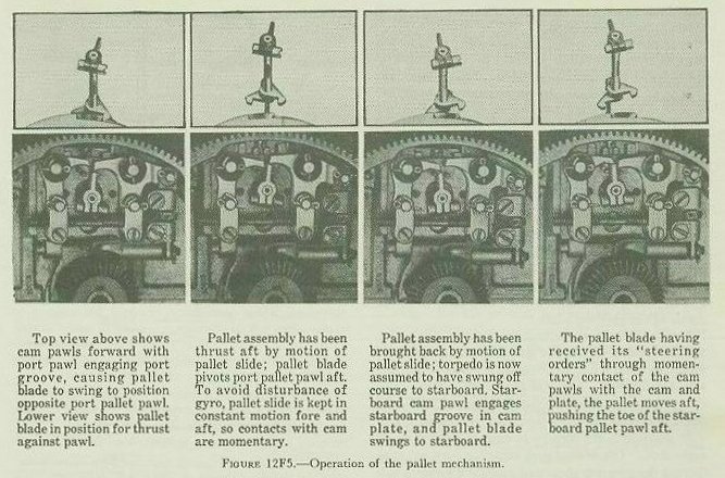 |
| Assume that the torpedo has turned off course to port. The gyro axis and cam are still pointing in the original direction; the torpedo has turned to port with respect to the gyro axis and cam. Because the pallet shaft is abaft the cam plate, it has moved to the starboard side of the cam. When the pallet shaft moves forward, the port cam pawl will strike the cam. The pallet shaft will turn counterclockwise (looking down from the top). The pallet blade will swing to starboard. When the pallet shaft moves aft, the pallet will strike the starboard pallet pawl and throw it aft. The linkage will move the port pallet pawl forward, and it will move the steering engine valve aft. The steering engine is so designed that when its valve is moved in one direction, its piston moves full-throw in the opposite direction. The piston will therefore move forward, carrying the piston fork and rudder rod with it. The rudder rod, through its yoke, will apply right rudder. The rudder will turn the torpedo back onto its course. Actually, the torpedo will not stop turning when it comes back on course. It will swing off course on the other side. The rudder will stay where it is until the steering engine gets the opposite order. And there will be no new order to the engine until the torpedo has crossed its course, so that the other cam pawl can strike the cam. Therefore, the track of the torpedo is not a straight line. The rudder oscillates constantly, and the torpedo weaves back and forth across its course. But because the pallet mechanism is sensitive, the weaving is small; the actual track is very close to a straight line. Summary. The pallet mechanism is driven by power taken from the forward propeller shaft. A part of the pallet mechanism makes a light, intermittent contact with the cam plate of the gyro. If the torpedo has turned off course, the mechanism will detect a change in the relative position of the cam plate. Then, through a mechanical linkage, it will send an appropriate order to the steering engine valve. The steering engine will respond by throwing the rudders in the direction necessary to bring the torpedo back on course. 12F7. Angle fire In the foregoing discussion, it has been assumed that the pallet shaft is always in line with the gyro axis, and that the pallet slide moves forward and aft. But those conditions exist only when the torpedo is fired with zero gyro angle. It is often inconvenient or impossible to launch a torpedo in the direction required by the solution to the torpedo fire control problem. This is especially true with fixed tubes. In such situations angle fire is used. The steering mechanism is set so that the torpedo, after it enters the water, will turn through the angle necessary to bring it onto its proper course. For an angle shot, the gyro angle is set through one of the gyro setting sockets on the outside of the torpedo. The socket, through a gear train, turns the gyro top plate through the desired gyro angle. (But note carefully that it does not move the gyro.) The top plate carries the whole pallet mechanism around with it. Since an eccentric cam drives the pallet slide, the slide will still have its back-and-forth motion in the new position. That motion will no longer be fore-and-aft, but it will still be toward and away from the center of the gyro top plate. |
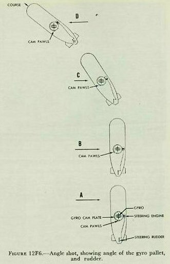 |
| Figure 12F6 shows the angle of the gyro, the pallet, and the rudder-for both a straight shot and an angle shot. In diagram A, the torpedo is ready to be fired on a straight shot. The gyro angle is set at zero. The cam pawls are in line with the gyro axis and the cam, ready to correct any deviation from the course. In diagram B, the torpedo is ready to be fired on an angle shot. The desired gyro angle has been set, thus turning the gyro top plate and moving the cam pawls away from the gyro axis. The angle between the cam pawls and the gyro axis is exactly the angle through which the torpedo will turn. Note that for an angle shot, as well as for a straight shot, the gyro axis is fore-and-aft at the moment of firing. In part C of figure 12F6, the torpedo is under way on an angle shot. The cam pawls have detected that the torpedo is off its set course. They have turned the pallet shaft, and the pallet mechanism has ordered left rudder. In the diagram, the rudder has turned the torpedo part way through the desired angle. And the cam pawls are part way around to the gyro axis. Notice that the gyro axis is still pointed in its original direction. In diagram D, the torpedo has straightened out on the course it was set for. The cam pawls have moved around into line with the gyro axis and the cam. The rudder is oscillating in the normal way. And the gyro axis is still pointing in the original direction. 12F8. Depth mechanism While the steering mechanism brings the torpedo onto its proper course and keeps it there, the depth mechanism brings it to its proper depth and keeps it there. The two horizontal depth rudders control the running depth of the torpedo. The depth engine, powered by compressed air from the reducing valve, operates the rudders. And the depth mechanism sends orders to the valve of the depth engine. |
| This system has two sensing parts-a hydrostatic diaphragm and a pendulum. The flexible diaphragm is open to sea water on one side; a spring resists the pressure of the water. The stronger the water pressure, the farther the diaphragm will move against the force of the spring. Since the pressure of the water depends on the depth, the position of the diaphragm can be used to indicate the depth at which the torpedo is running. Because the pendulum responds to gravity, and tends to hang straight down, it can determine the angle at which the torpedo is changing depth. The diaphragm and pendulum work together to send orders to the depth engine. There are two reasons why the depth engine may need new orders. First, the torpedo may be running at the wrong depth. Second, it may be changing its depth at too steep an angle. Assume the torpedo is running below its preset depth. The diaphragm responds to the extra water pressure, and sends an up rudder order to the depth engine. The torpedo begins to climb. If the engine gets no further orders, the torpedo will be climbing fast when it reaches the right depth, and it will overshoot. Then the diaphragm will send a down rudder order. The torpedo will go down and overshoot again. So, if the torpedo is going to make a successful run, the depth mechanism must control not only its depth, but also the rate at which it changes depth. |
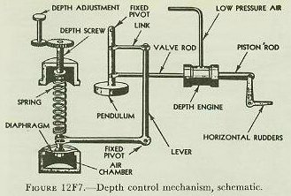 |
| Figure 12F7 shows schematically how the diaphragm and pendulum work together. Under the diaphragm is a sealed chamber of air. Sea water reaches the upper surface of the diaphragm through suitable passages, and tends to push it down. The spring, being under tension, resists this downward pressure. (The depth at which the torpedo will run is set by adjusting the tension of this spring.) To see how the mechanism works, assume that the torpedo is below its set depth, with its axis horizontal. Water pressure pushes the diaphragm down, against the force of the spring and the resistance of the air trapped in the chamber. The downward movement of the diaphragm rocks the diaphragm lever counterclockwise. Since the diaphragm has only a limited movement, the lever is pivoted near the diaphragm, so that it multiplies the diaphragm movement by a factor of 18. |
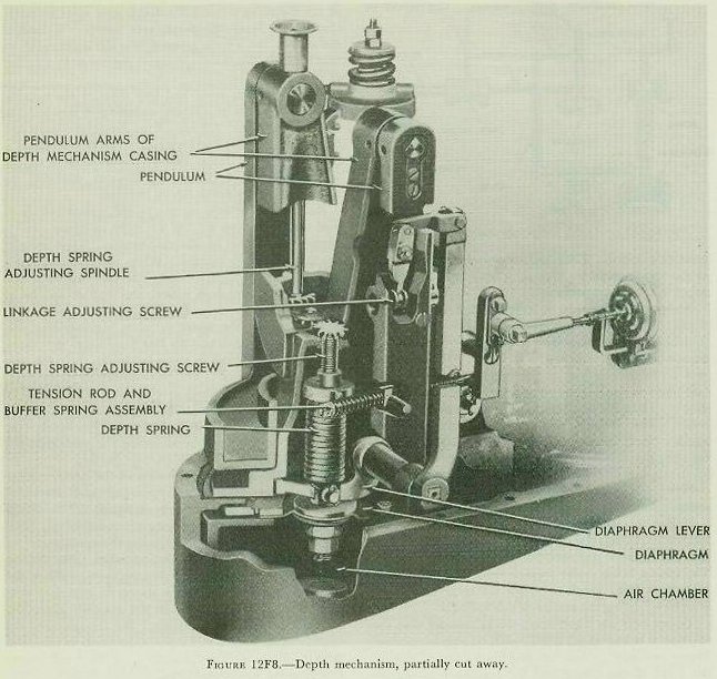
| The pendulum lever and link transfer the rocking movement to the pendulum, swinging it forward (to the left in figure 12F7). The pendulum pulls the depth engine valve rod forward. The depth engine is built so that its piston follows the movement of the valve. So the piston moves forward, applying up rudder, and the torpedo begins to climb. But as the torpedo turns upward, gravity tends to pull the pendulum aft (to the right in figure 12F7), against the action of the diaphragm. That reduces the amount of up rudder. When the climbing angle is just steep enough to make the diaphragm action balance the pendulum action, the rudder will be in neutral. But the torpedo will still be climbing. As it climbs, the water pressure becomes less. So the downward pressure on the diaphragm decreases. That lets the pendulum move farther to the right, and apply down rudder. The torpedo begins to level off, and reaches its set depth at a slow rate of climb. In that way, the pendulum tends to prevent overshooting. And the torpedo runs at a nearly uniform depth-the depth set before firing by adjusting the tension on the diaphragm spring. Figure 12F8 is a cutaway view of the depth mechanism. It shows the actual appearance and location of the parts shown schematically in figure 12F7. These two figures should be carefully compared. Like the steering engine, the depth engine works on compressed air from the reducing valve. But the two engines differ considerably in operation. When the valve of the steering engine moves in one direction, the piston goes full-throw in the opposite direction. It has no in-between positions. But the piston of the depth engine moves in the same direction as its valve. And it follows the valve exactly. So the depth engine can hold the horizontal depth rudders at any position between full up and full down. |
 |