| NAVAL ORDNANCE AND GUNNERY VOLUME 2, FIRE CONTROL CHAPTER 16 RADAR AND OPTICS |
| INDEXCHAPTER 16 RADAR AND OPTICS A. Introduction B. Principles of radar C. Types of radar equipment D. Special purpose equipments E. Principles of optics F. Types of optical equipment G. Combat information center (CIC) |
| B. Principles of Radar 16B1. Definition The word RADAR is formed as an abbreviation for Radio Detection And Ranging. It is an electronic device that may be used to detect the presence of objects like airplanes or ships even in darkness, fog, or storm. In addition to indicating their presence, radar may be used to determine their bearing, distance, elevation, and speed; and to enable the operator to recognize their general character. It is one of the greatest scientific developments that has emerged from World War II. Its development, like that of most great inventions, was mothered by necessity, that of detecting the enemy before he detected us. The basic principles upon which its functioning depends are relatively simple, and the seemingly complicated series of electrical events encountered in radar can be resolved into a logical series of functions which, taken individually, may be identified and understood. 16B2. Sound-wave reflection The principle upon which radar operates is very similar to the principles of sound echoes or wave reflection. If a person shouts in the direction of a cliff, or some other sound-reflecting surface, he hears his shout “return” from the direction of the cliff. What actually takes place is that the sound waves, generated by the shout, travel through the air until they strike the cliff. There they are reflected or “bounced off,” and some are returned to the originating spot, where the person is then able to hear the echo. Some time elapses between the instant the sound originates and the time when the echo is heard because sound waves travel through air at approximately 1,100 feet per second. The farther the person is from the cliff, the longer this time interval will be. If a person is 2,200 feet from the cliff when he shouts, about 4 seconds elapse before he hears the echo, that is, 2 seconds for the sound waves to reach the cliff and 2 seconds for them to return. |
 |
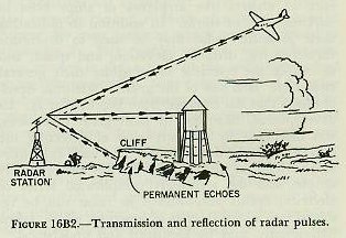 |
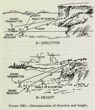
| If a directional device is built to transmit and receive sound, the principles of echo, together with a knowledge of the velocity of sound, can be used to determine the direction, distance, and height of a cliff such as is shown in figure 16B1. A sound transmitter, which can generate pulses of sound energy, can be so placed at the focus of a reflector that it radiates a beam of sound. The sound receiver can be a highly directional microphone located inside a reflector (at its focal point, and facing the reflector) to increase the directional effect. The microphone is connected through an amplifier to a loudspeaker. Then to determine the distance and direction of the cliff, the transmitting and receiving apparatus are placed so that the line of travel of the transmitted sound beam and the received echo will very nearly coincide. They would coincide exactly if the same reflector could be used for both transmitting and receiving, as is done in radar systems. The apparatus (both the transmitter and receiver) are rotated until the maximum volume of echo is obtained. The horizontal distance to the cliff can then be computed by multiplying one-half of the elapsed time in seconds by the velocity of sound. This will be essentially the distance along the line RA (figure l6BI). If the receiver has a circular scale that is marked off in degrees, and if it has been properly oriented with a compass, the direction or azimuth of the cliff is also shown. Thus, if the angle indicated on the scale is 45°, the cliff is northeast from the receiver position. To determine height (fig. 16B1), the transmitter and receiver antennas are tilted from the horizontal position (shown by dotted lines) while still pointing in the same direction. At first the echo is still heard, but the elapsed time is increased slightly. As the angle of elevation is increased more, an angle is found where the echo disappears. This is the angle at which the sound is passing over the top of the cliff and is therefore not reflected back to the receiver. The angle at which the echo just disappears is such that the apparatus is pointing along solid line RB. If the receiver is equipped with a scale that permits a determination of the angle of elevation, the height of the cliff, AB, can be calculated from the angle and either distance RA or RB, by the use of one of the basic trigonometric ratios. 16B3. Radio-wave reflection All radar sets work on a principle very much like that described for sound waves. In radar sets, however, a radio wave of extremely high frequency is used instead of a sound wave. The energy sent out by a radar set is similar to that sent out by an ordinary radio transmitter. See figure 16B2. |
| The radar set has one outstanding characteristic different from a radio in that it picks up its own signals. It transmits a short pulse and receives its echoes, then transmits another pulse and receives those echoes. This out-and-back cycle is repeated 60 to 4,000 times per second, depending on the design of the set. For Navy use the repetition rate is generally less than 1,000 cps. If the outgoing wave is sent into clear space, no energy is reflected back to the receiver. The wave and energy that it carries simply travel out into space and are lost for all practical purposes. If, however, the wave strikes an object such as an airplane (fig. 16B2), a ship, a building, or a hill, some of the energy is sent back as a reflected wave. If the object is a good conductor of electricity and is large compared to a quarter-wavelength of the transmitted energy, a strong echo (but only a very small fraction of the transmitted energy) is returned to the antenna. If the object is a poor conductor or is small, the reflected energy is small and the echo is weak. Radio waves travel at the speed of light, approximately 186,000 land miles per second or 162,000 nautical miles per second. Radio waves of the u-h-f and s-h-f band travel in straight lines. Accordingly, there will be an extremely short time interval between the sending of the pulse and the reception of its echo. It is possible, however, to measure the interval of elapsed time between the transmitted and received pulse with great accuracy, even to one ten-millionth of a second (1 x 10 to the 7th power seconds). The forming, timing, and presentation of radar pulses are accomplished by a number of special circuits and devices. The directional antennas employed by radar equipment transmit and receive energy in a fairly sharply defined beam. Therefore, when a signal is picked up, the antenna can be rotated until the received signal is maximum. The direction of the target is then determined by the position of the antenna. The echoes received by the radar receiver appear as marks of light on an oscilloscope (called “scope” for short). This scope may be marked with a scale of miles (or yards), or degrees, or both. Hence, from the position of a signal echo on the scope, an observer can tell the range and bearing of the corresponding target. 16B4. Radar methods 1. Continuous-wave method. The continuous-wave method of detecting a target makes use of the Doppler effect. The frequency of a radar echo is changed when the object which reflects the signal is moving toward or away from the radar transmitter. This change in frequency is known as the Doppler effect. A similar effect at audible frequencies is recognized readily when the sound from the whistle of an approaching train appears to the ear to increase in pitch. The opposite effect occurs when the train is moving away from the listener. The radar application of this effect permits a measurement of the difference in frequency between the transmitted and reflected energy and thus a determination of both the presence and speed of the moving target. This method works well with fast-moving targets, but not well with those that are slow or stationary. C-w systems are therefore limited in present usage. 2. Frequency-modulation method. In the frequency-modulation method the transmitted energy is varied continuously and periodically over a specified band of frequencies. The instantaneous frequency of the energy being radiated by the antenna, therefore, differs from the instantaneous frequency received by the antenna from the target. The frequency difference depends on the distance traveled and can be used as a measure of range. Moving targets produce a frequency shift in the returned signal because of the Doppler effect, however, and this affects the accuracy of range measurement. This method, therefore, works better with stationary or slow-moving targets than with fast-moving ones. 3. Pulse-modulated method. In the pulse-modulation method the r-f energy is transmitted in short pulses in which the time duration may vary from 1 to 50 microseconds, if the transmitter is turned off before the reflected energy returns from the target, the receiver can distinguish between the transmitted pulse and the reflected pulse. After all reflections have returned, the transmitter can be turned on again and the process repeated. The receiver output is applied to an indicator that measures the time interval between the transmission of the energy and its return as a reflection. Because the energy travels at a constant velocity, one-half the time interval becomes a measure of the distance traveled by the pulse to the target, or the range. Because this method does not depend on the relative frequencies of the emitted and returned signals or on the motion of the target, difficulties experienced in the c-w and f-rn methods are not present. The pulse-modulation method is used almost completely in military applications. Therefore, it will be the only method discussed in this text. 16B5. Uses of radar Radar equipments fall into three general classifications: (1) search, (2) fire-control, and (8) fighter-director (air control). Search radars are of two categories: (1) air search and (2) surface search. These equipments are for general navigation use and early warning networks. Fire-control radars are confined more specifically to use with certain groups or types of gun batteries and are designed to fit the requirements of the battery with which they are used. Fighter-director radars are specifically designed to control and direct aircraft in air-to-air attack and defense. These radars are also used as search equipments in some instances. |
 |
 |
 |
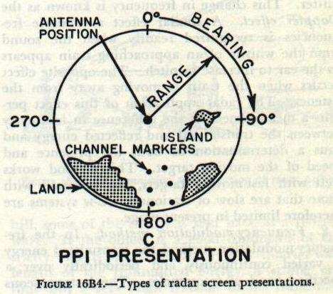 |
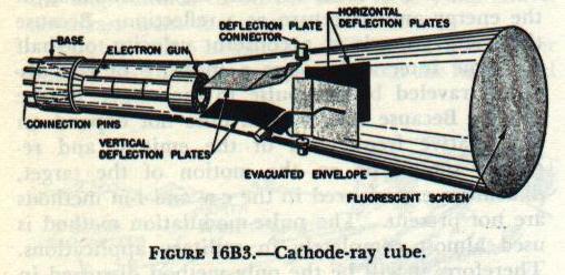
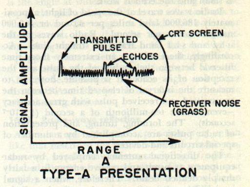
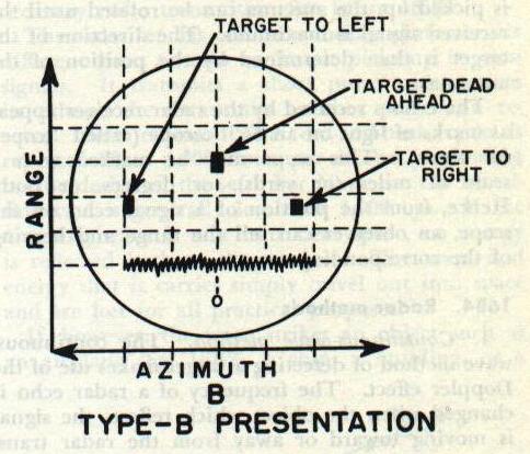
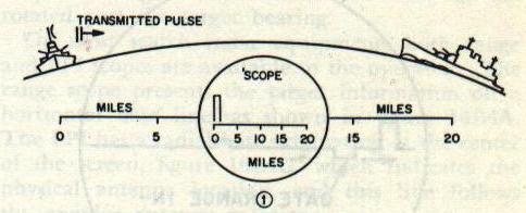
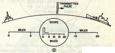
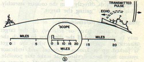
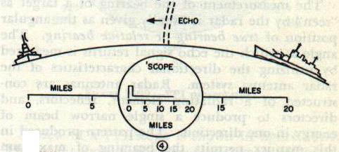
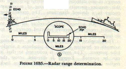
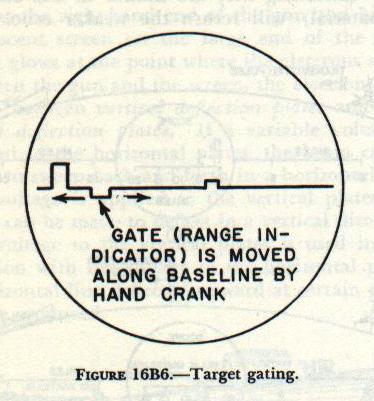
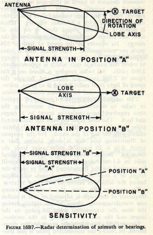
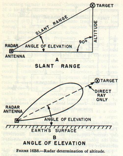
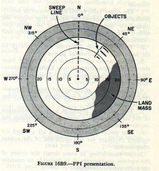
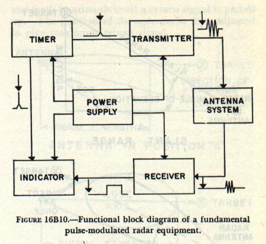
| 16B6. Types of presentation To furnish usable intelligence, a radar set must have some type of visual presentation of the target echo for the operator to observe. Cathode-ray tubes are used for this purpose. The cathode-ray tube is a special type of vacuum tube which acts as an electronic stop watch. As shown in figure 16B3, electrons are channeled into a narrow beam by an electron gun in the neck of the tube. The electrons shoot out of the small hole at the right-hand end of the gun and hit the fluorescent screen on the large end of the tube, which glows at the point where the electrons strike. Between the gun and the screen, the electron beam passes between vertical deflection plates and horizontal deflection plates. If a variable voltage Is applied to the horizontal plates, the beam can be made to sweep back and forth in a horizontal line. If a voltage is applied to the vertical plates, the beam can be made to deflect in a vertical direction. If a voltage to the vertical plates is used in conjunction with the voltage to the horizontal plates, a horizontal line deflected upward at certain points can be produced. Type-A presentation is used to determine range, and the scope has short persistence (a target indication remains on the scope face only instantaneously). The echo causes a vertical displacement of the spot. The amplitude of the displacement depends on the strength of the returned signal pulse. The point on the horizontal base line at which the vertical displacement occurs indicates the range. Type-A presentation is shown in figure 16B4A. The Type-B presentation (fig. 16B4B) indicates both range and azimuth angle. The vertical displacement of the echo signal indicates range, and the horizontal displacement of the echo signal indicates azimuth angle. This scope has medium to long persistence. Type PPI (plan position indicator) presentation, shown in figure I6B4C, also indicates range and azimuth angle. In this type of presentation the electron beam is swept radially from the center of the scope to the outer edge. The sweep line follows the antenna rotation. In effect, a picture of surrounding objects is painted” on the screen. This scope has medium persistence. 16B7. Range determination The successful employment of pulse-modulated radar systems depends primarily on the ability to measure distance in terms of time and on a knowledge of the velocity of light. Radio-frequency energy, once it has been radiated into space, continues to travel with a constant velocity. When it strikes a reflecting object there is no loss of time, but merely a redirecting of a portion of the energy. Its velocity at the speed of light is 328 yards per microsecond. This means that it takes approximately 6.1 microseconds of radio energy to travel one nautical mile which is approximately 2,000 yards. All radar ranging is based on a flat figure of 2,000 yards per mile, and, because the speed of light (and radio waves) is so great, microseconds (ps) are used for all time determinations. This constant velocity of r-f energy is applied in radar to determine range by measuring the time required for a pulse to travel to a target and back. The time lapse between the transmitted pulse and the echo return may be readily determined with the aid of the scope. For the purpose of illustrating how this is done, assume that a target ship is 20 nautical miles away from the radar set. Because radio energy travels 1 nautical mile in 6.1 microseconds, 122 microseconds will be required for the transmitted pulse to reach the target, or a total of 244 microseconds will elapse before the echo will return to the radar receiver. To measure this time, the horizontal sweep frequency of the scope is adjusted so that it makes one complete sweep (from left to right) during the time the transmitted pulse is going to the target and the echo is returning to the receiver. Figure l6B5 shows how the range is then determined. In 16B5-1 the transmitted pulse is just leaving the antenna. A part of the generated energy is fed to the vertical deflection section of the scope tube at the instant the pulse is transmitted and causes a vertical line (pip) to appear at the zero-mile mark on the scope. In 16B5-2, 61 microseconds later, the transmitted pulse has traveled 10 miles toward the target. The horizontal trace on the scope, however, has reached only the 5-mile mark, that is, one half the distance the transmitted pulse has traveled. In figure 16B5-3, 122 microseconds after start, the transmitted pulse has reached the target 20 miles away and the echo has started back. Scope now reads 10 miles. In figure 16B5-4, 183 microseconds after start of initial pulse, the echo has returned half the distance from the target, and the scope reading is 15 miles. In 16B5-5, 244 microseconds after the initial pulse, the echo has returned to the receiver. An echo pip, of smaller amplitude than the initial transmitter pip, is displayed on the scope at the 20-mile mark. If two or more targets are in the path of the transmitted pulse, each will return a portion of the incident energy as echoes. The target farthest away (assuming they are similar in size and type of material) will return the weaker echo. The foregoing are the basic principles of all ranging scope determinations. Usually in conjunction with the scope there is a hand crank and mechanical counter assembly. When a target is indicated on the base line, the operator turns the hand crank to move the range indicator, or gate (fig. 16B6), to the target and then reads the range, in yards, directly from the counter assembly. This is called “gating the target.” 16B8. Bearing determination The bearing (true or relative) of the target may be determined if the direction in which the directional antenna is pointing when the target is picked up is known. Control and indicator systems have been devised that make this possible. The measurement of the bearing of a target as “seen” by the radar is usually given as the angular position of true bearing or relative bearing. The angle at which the echo signal returns is measured by utilizing the directional characteristics of the radar antenna system. Radar antennas are constructed of a radiating element, reflectors, and directors to produce a single narrow beam of energy in one direction. The pattern produced in this manner permits the beaming of maximum energy in a desired direction. The transmitting pattern of an antenna system is also its receiving pattern. An antenna can therefore be used to transmit energy, to receive reflected energy, or to do both. The simplest form of antenna for measuring azimuth or bearing is one that produces a single-lobe pattern. The system is mounted so that it can be rotated. Energy is directed across the region to be searched by moving the beam back and forth in azimuth until a return signal is picked up. The position of the antenna is then adjusted to give maximum return signal. Figure 16B7 shows the receiving pattern for a typical radar antenna. In this figure, relative signal strength is plotted against the angular position of the antenna with respect to the target. A maximum signal is received only when the axis of the lobe passes through the target. The sensitivity of this system depends on the angular width of the lobe pattern. The operator adjusts the position of the antenna system for maximum received signal. If the signal strength changes appreciably when the antenna is rotated through a small angle, the accuracy with which the on-target position can be selected is great. Thus, in figure 16B7, the relative signal strengths A and B have very little difference. If the energy is concentrated in a narrower beam, the difference is greater and the accuracy better. 16B9. Altitude determination The remaining dimension necessary to locate completely an object in space can be expressed either as an angle of elevation or as an altitude. If one is known, the other can be calculated from one of the basic trigonometric ratios. A method of determining the angle of elevation or the altitude is shown in figure 16B8. The slant range (fig. 16B8A) is obtained from the radar scope indication as the range to the target. The angle of elevation is that of the radar antenna (fig. 16B8B). The altitude is equal to the slant range multiplied by the sine of the angle of elevation. In radar equipments with antennas that may be elevated, altitude determination by slant range is automatically computed electronically. In equipments (air search) where the antennas do not elevate, the altitude is automatically computed from the time lapse between two echoes, one that is returned directly to the antenna and one that returns to the earth and then reflects to the antenna. 16B10. Plan position indicator The range scope has certain limitations when it is desired to know what is happening instantaneously in all directions because it indicates only the targets in the direction which the antenna is instantaneously pointing. A master PPI, however, allows the radar operator to see the screen images of all objects surrounding his craft (within the range limitations of the equipment) because it displays a graphic plot of 3600 of antenna rotation and has a screen of the necessary persistence to keep the targets visible after the antenna has rotated past the target bearing. On most search radar equipments both range and PPI scopes are available to the operator. The range scope presents the target information on a horizontal base line, as shown in figure 16B4A. The PPI has a radial base originating at the center of the screen, figure 16B4C, which indicates the physical antenna location, and this line follows the angular antenna rotation. A view of a PPI scope is shown in figure 16B9. The bright spots on the screen are images of objects (ships, planes, land masses, and the like) in the vicinity of the craft carrying the PPI equipment. Around the outer edge of the scope are relative and true bearing circles. Spaced evenly across the face of the tube are range circles, calibrated in miles. Thus, from the position of the images, their approximate range and bearing may be determined from the scope. A particular object of interest may be singled out for more accurate ranging by referring to the range scope. l6B11. Functional components Radar systems now in existence vary greatly in detail. They may be very simple, or, if more accurate data are required, they may be highly refined. The principles of operation, however, are essentially the same for all systems. Thus a single basic radar system can be visualized in which the functional requirements are basically the same as for all specific equipments. In general, the degree of complication o radar circuits increases with the frequency. The microwave region lends itself to a higher degree of precision in angular measurement and for this reason modern radars operate at superhigh frequencies. The functional breakdown of a pulse-modulated radar system generally includes six major components as shown in the block diagram of figure l6BlO. The components may be summarized as follows: 1. The timer (also called synchronizer or keyer) produces the synchronizing signals that trigger the transmitter the required number of times per second. It also triggers the indicator sweep and coordinates the other associated circuits. 2. The transmitter generates the r-f energy in the form of short powerful pulses. 3. The antenna system takes the r-f energy from the transmitter, radiates it in a highly directional beam, receives any returning echoes, and passes these echoes to the receiver. 4. The receiver amplifies the weak r-f pulses returned by a target and reproduces them as video pulses to the indicator. 5. The indicator produces a visual indication of the echo pulses in a manner that furnishes the required information. 6. The power supply furnishes all a-c and d-c voltages necessary for the operation of the system components. Before considering in more detail the action of the various equipments, it is desirable to consider the radar system constants. 16B12. Radar system constants Any radar system has associated with it certain constants such as carrier frequency, pulse-repetition frequency (the number of pulses sent out per second), pulse width (in microseconds), and power relation (relationship of peak and average power). The choice of these constants for a particular system is determined by its tactical use, the accuracy required, the range to be covered, the practical physical size, and the problem of generating and receiving the signals. 1. Carrier frequency. The carrier frequency is the frequency at which the r-f energy is generated. The principal factors influencing the selection of the carrier frequency are the desired directivity and the generation and reception of the necessary microwave r-f energy. For the determination of direction and for the concentration of the transmitted energy so that a greater portion of it is useful, the antenna should be highly directive. The higher the carrier frequency, the shorter the wavelength and hence the smaller is the antenna array for a given sharpness of pattern, because the individual radiating element is normally a half-wave long. For an antenna array of a given physical size the pattern is sharper for a higher frequency. The problem of generating and amplifying reasonable amounts of r-f energies at extremely high frequencies is complicated by the physical construction of the tubes to be used. The common tube becomes impractical and must be replaced by tubes of special design. Among these are such types as the magnetron, klystron, lighthouse triode, doorknob, acorn and peanut tubes. These tubes of special design are normally much smaller than the conventional tubes. One of the problems involved in reducing the size of a tube is the reduction in the power rating of the tube. For example, r-f generators, such as the magnetron, are designed to radiate a large amount of power during a relatively short pulse time. Carrier frequencies may be of the order of 100 megacycles and above. It is very difficult to amplify microwave signals; as a result, r-f amplifiers are not employed. Instead, the frequency of the incoming signals is mixed (heterodyned) with that of a local oscillator in a crystal mixer to produce a difference frequency called the intermediate frequency (i-f). This intermediate frequency is low enough to be amplified in suitable i-f amplifier stages employing electron tubes. 2. Pulse-repetition frequency. Sufficient time must be allowed between each transmitted pulse for an echo to return from any target located within the maximum workable range of the system. Otherwise the reception of the echoes from the more distant targets would be obscured by succeeding transmitted pulses. Therefore, the maximum range of a given equipment depends on the ratio of the resting time to the pulse width, provided the peak power is sufficient to return a usable echo. This necessary time interval fixes the highest pulse-repetition frequency that can be used. |
 |
 |
 |
 |
 |
 |
 |
 |
 |
 |
| In a system in which the indicator is operative during the entire interval between transmitted pulses, the repetition frequency must be very stable if accurate range measurement is desired. Because the oscilloscope screen will normally have a medium long persistence, successive traces should appear in exactly the same position to avoid blurring. 3. Pulse width. The minimum range at which a target can be detected is determined largely by the width of the transmitted pulse. If a target is so close to the transmitter that the echo is returned to the receiver before the transmitter is turned off, the reception of the echo obviously will be masked by the transmitted pulse. For example, a pulse width of 1 micro second will have a minimum range of 164 yards, meaning that a target within this range will not show because it will be “blocked out’ on the screen. In this respect, equipments for “close in” ranging or navigation work use pulses of the order of 0.1 microsecond. For long-range equipment the pulse width is normally from 1 to 5 microsecond. 4. Power relation. A radar transmitter generates r-f energy in the form of extremely short pulses and is turned off between pulses for comparatively long intervals. The useful power of the transmitter is that contained in the radiated pulses and is termed the peak power of the system. Power is normally measured as an average value over a relatively long period of time. Because the radar transmitter is resting for a time that is long with respect to the operating time, the average power delivered during one cycle of operation is relatively low compared with the peak power available during the pulse time. A definite relationship exists between the average power dissipated over an extended period of time and the peak power developed during the pulse time. The overall time of one cycle of operation is the reciprocal of the pulse-repetition frequency (PRF). Other factors remaining constant, the greater the pulse width, the higher will be the average power; and the longer the pulse repetition time, the lower will be the average power. Thus, average power/peak power = pulse width/pulse-repetition time The operating cycle of the radar transmitter can be described in terms of the fraction of the total time that r-f energy is radiated. This time relationship is called the duty cycle and may be represented as: duty cycle = average power/peak power = pulse width/ pulse-repetition time High peak power is desirable in order to produce a strong echo over the maximum range of the equipment. Low average power enables the transmitter tubes and circuit components to be made smaller and more compact. Thus, it is advantageous to have a low duty cycle. The peak power that can be developed is dependent upon this interrelation between peak and average power, pulse width and pulse-repetition time, or in other words, the duty cycle. |