| NAVAL ORDNANCE AND GUNNERY VOLUME 2, FIRE CONTROL CHAPTER 19 SURFACE FIRE CONTROL PROBLEM |
| HOME INDEX Chapter 19 SURFACE FIRE CONTROL PROBLEM A. General B. Analytical solution C. Graphic rangekeeping D. Mechanical solution-general E. Basic mechanisms F. Mechanical solution-basic rangekeepers G. Mechanical solution-establishing the horizontal plane |
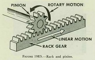
| E. Basic Mechanisms 19E1. Introduction The study of any computer should be based on an understanding of the various basic mechanisms of which it is composed. These devices perform the mathematical computations essential to solution of the fire control problem. The present discussion will be limited to the most important basic mechanisms. Mechanisms are represented by conventional symbols which facilitate their presentation on functional diagrams. Since the understanding of such diagrams is essential to the officer performing gunnery duties, these symbols are included in the figures depicting each mechanism. 19E2. Shafts The computer receives inputs, performs computations, and transmits outputs. These quantities are in various units such as yards of range, degrees of elevation, knots of ship speed. Since, however, each of these quantities can be expressed as a number, it is possible to translate all quantities to shaft rotation. This procedure not only provides mechanical representation of the quantity; it also makes it easy to change or modify the quantity by suitable rotation. As the value of an input (such as own-ship speed) changes, the values of the computed quantities will change accordingly. These changes must be carried instantaneously and continuously to all the mechanisms affected by the change of input. These changing values are carried from one mechanism to another by shaft rotation. Turning a shaft changes the value of the angle, speed, or distance represented by the position of that shaft. Rotation in one direction increases the value represented, and is considered positive; rotation in the other direction decreases the value, and is negative. From this, it follows that every shaft has a zero position, even though, as is sometimes true, the shaft may be restrained from reaching the zero position. One revolution of a shaft can represent any convenient amount of change in the given quantity. For example, one revolution of the elevation shaft may represent a 3-degree change in elevation. On a range shaft, one turn may represent 100 yards of range. The value that a shaft carries in one revolution is called shaft value. Total value carried by a shaft is the shaft value multiplied by the number of revolutions made by the shaft from its zero position. |
 |
 |
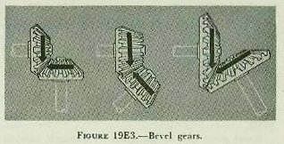 |
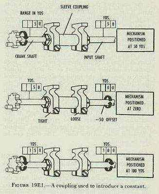
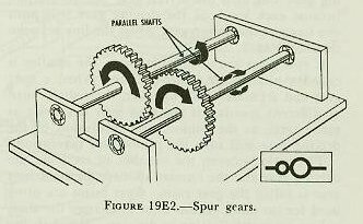
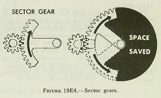
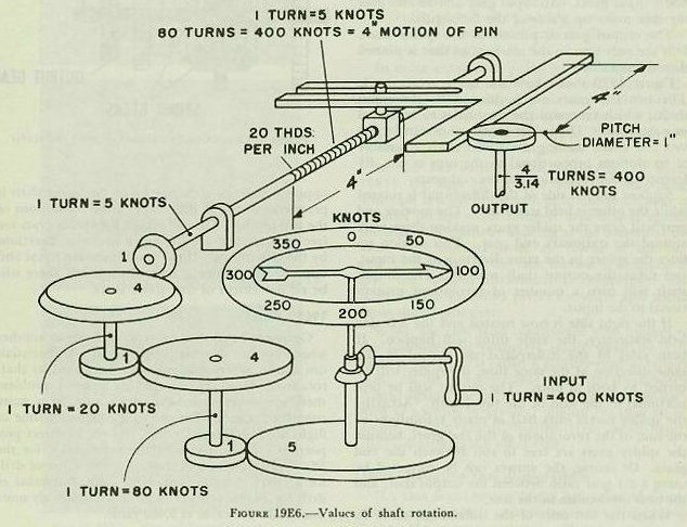
| It is sometimes necessary to add or subtract a constant from a value carried by a shaft. For example, in the computer the value of range minus a constant is used. In this instance the crank input is range, but the mechanism is positioned for range minus K. The constant K can be set into the transmission line by a sleeve coupling or a clamp, as is shown in figure 19E1. Here a sleeve coupling joins two shafts which must introduce into the mechanism range in yards minus a constant of 50 yards. Each shaft has a counter showing its position. Both shafts are initially positioned at 50 yards. If one clamp is loosened, the input shaft can be turned until its counter reads zero without moving the crankshaft. If the clamp is now tightened, with the value of 50 yards on the crankshaft and zero on the input shaft, the two shafts will turn together when the crank is turned, but the input to the mechanism will always be 50 yards less than the crank input. This use of a clamp is called �putting a constant offset on the line.� The offset can be plus or minus. 19E3. Gears Gears are wheels with mating teeth cut so that one can turn the other without slipping. If two mating gears are the same size, they will have the same number of teeth. One revolution of the driving gear will turn the driven gear one revolution, because each tooth of the driving gear will push one tooth of the driven gear across the line between their centers. If two gears are of different sizes, the smaller is called a pinion, the larger a spur. When a spur gear and a pinion mesh together, their shafts turn at different speeds. If the spur gear has twice as many teeth as the pinion, one revolution of the driving gear will turn the pinion two revolutions. The ratio between the number of teeth on the driving gear and the number of teeth on the driven gear is called the gear ratio. Gear ratios are often used for no other reason than to change the shaft values, by multiplication or division. If a shaft has a value of 500 yards per revolution, this can be reduced to 50 yards per revolution by a 1:10 gear ratio. Although there are many different types of gears, most of those used in fire control installations are of three types: spur gears, bevel gears, and sector gears. Spur gears are used to connect parallel shafts and transmit motion in opposite directions, as in figure 19E2. Bevel gears can be designed to transmit motion between shafts at almost any angle to one another, as indicated in figure 19E3. By using bevel gears, several shafts at different angles can be driven by one driving shaft. Sometimes only a part of a gear is needed, where the motion of the pinion is limited. In this case, space is saved by the use of a sector gear, illustrated in figure 19E4. A special type of sector gear is the rack, frequently used to convert rotary motion to linear motion. A rack is a straight bar with gear teeth cut in it, as shown in figure 19E5. If the rack drives a gear, it converts linear motion into rotary motion. The rack is restrained by guide rails which permit motion in one line only. The position of a rack indicates a value by the amount it has moved from zero. It must be understood that motion of a shaft, rack, gear, or dial has no meaning except that assigned by the designer. It is not difficult to design an assembly so that proper values are entered and transmitted. For example, the conversion constant 0.563, which converts knots to yards per second, is applied by a gear ratio. (A close approximation can be obtained by a gear ratio of 22:39, which equals 0.564.) The mechanism shown in figure l9E6 will serve to illustrate some of the principles presented in this section. The sequence starts with an input shaft, one turn of which represents 400 knots. The ratios of the gears have been designed to use the 4-inch motion of the rack, which is driven by a screw with 20 threads to the inch. Since each revolution of the screw shaft represents 5 knots, each inch the screw (and therefore the rack) moves equals 100 knots, and 4-inch travel of the rack represents 400 knots. It is possible to transform the output of the rack (linear motion) to shaft rotation as shown. If an output shaft carrying a gear with pitch diameter of 1 inch is used, one revolution of this output shaft will represent or 3.14 inches of linear motion of the rack. The value 4/3.14 turns of the output shaft will then represent 400 knots. |
 |
 |
 |
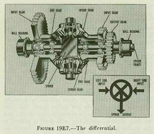
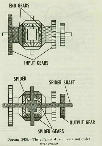
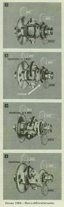
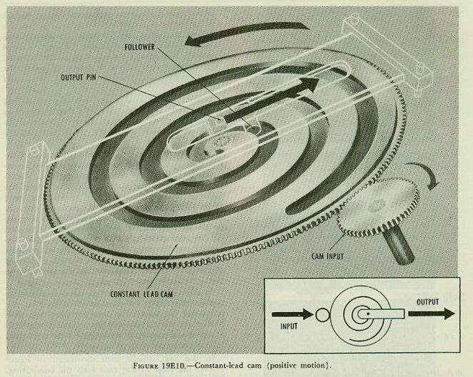
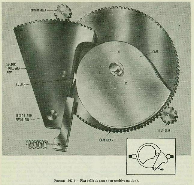
| 19E4. Differentials A differential is a mechanism that can perform addition and subtraction. More precisely, it adds the total revolutions of two shafts or subtracts the total revolutions of one shaft from the total revolutions of another shaft, and delivers the answer by positioning a third shaft. A differential will add or subtract any number of revolutions, or fractions of single revolutions, continuously and accurately. As inputs change, it produces a series of answers. Figure 19E7 is a cut-away drawing of a bevel-gear differential, showing the relation of all its parts. Grouped around the center of a mechanism are four bevel gears, meshed together. These four gears and the spider shaft are the heart of the differential. The two bevel gears on either side are the end gears; the two bevel gears above and below, meshing with the end gears, are the spider gears; the cross shaft and the spider gears constitute the spider, and the long shaft to which the cross shaft is pinned is the spider shaft. All gears are free to rotate on precision bearings. The three spur gears in figure 19E8 are used to connect the two end gears and the spider shaft to other mechanisms. They may be of any convenient size. The two attached to the end gears are normally input gears. An input gear and an end gear together make up a side of the differential. The output gear is pinned to the spider shaft. It is the only gear in the mechanism that is pinned directly to a shaft. Figure l9E9 shows how the spider gears work. The two end gears are positioned by the input shafts, which represent the quantities to be added or subtracted. The spider gears are driven by the two end gears, turning the spider shaft a number of revolutions proportional to the sum or the difference of the revolutions of the end gears. Suppose the left side of the differential is rotated while the other is held stationary. The moving end gear will drive the spider gears, making them walk around the stationary end gear. This motion rotates the spider in the same direction as the input, and turns the output shaft with it. The output shaft will turn a number of revolutions proportional to the input. If the right side is now rotated and the left side held stationary, the same thing will happen. If both sides of the differential are turned in the same direction at the same time, the spider will be turned by both at once. The output will be proportional to the sum of the two inputs. Actually, the spider makes only half as many revolutions as the sum of the revolutions of the end gears, because the spider gears are free to roll between the end gears. Of course, the answer can be corrected by using a 2:1 gear ratio between the output shaft and the next mechanism in the line. When the two sides of the differential move in opposite directions, the output on the spider shaft is proportional to the difference of the revolutions of the two inputs. This is because the spider gears are free to turn, and are driven in opposite directions by the two inputs. If the two inputs are equal and opposite, the spider gears will turn, but there will be no movement of the spider shaft. 19E5. Cams Gears can be used to convert one value to another when they are directly proportional. Differentials can add or subtract quantities represented by shaft rotation. However, in the fire control problem there are other functions which vary in a more complex manner. For example, drift and time of flight are functions of range, but not in direct proportion. Examination of the range table for the 5�/38 caliber gun will show that the value of drift for a range of 5,000 yards is 10 yards, but value of drift for 10,000 yards is 69 yards, considerably more than twice the value at 5,000 yards. To obtain the correct mechanical output of drift for the values of range, a cam is used. A cam is a rotating or sliding device whose operating surface is cut to give the desired output for every value of input. The output is taken off by a cam follower. The follower may ride in a groove or slot in the cam face, or it may ride on the outside contour of the cam. One simple cam has a uniform or constant-lead spiral groove cut in the face of a disc as shown in figure 19E10. Each point on the spiral corresponds to an output that is directly proportional to the input. If the constant-lead cam is rotated in one direction, the spiral will force the follower block outward from the center along a straight slot. Turning the plate in the opposite direction forces the follower toward the center. The follower itself never travels to the center of the cam, but the output pin is offset on the follower block so that it can be positioned directly over the center of the cam for the zero position. The cam output is the distance from the center of the cam to the output pin, and can be picked off by a slide or rack. The output of the constant-lead cam is directly proportional to the input. In other cams, each point on the output surface represents a more complex function, such as the reciprocal, the square, or some empirical function. Such cams are called computing cams to set them apart from the constant-lead type. Most cams used in computers are computing cams. In the flat ballistic cam illustrated in figure l9E11, the edge of the cam does the computing. The cam is fixed to the cam gear and turns with it. A roller on the sector follower arm is held against the edge of the cam by a spring at the bottom of the arm. The distance from the center of the cam gear to the edge of the cam surface is designed to give the desired functional relationship. The movement of the roller pivots the sector arm which turns the output gear. When the cam is so constructed that motion of the follower will positively result when the cam plate is moved, it is called a positive-motion type of cam. In the non-positive-motion type the follower is held against the cam surface by some acting force such as a spring or gravity. Figure 19E10 is an example of the positive-motion type, while figure l9El1 illustrates the other type. |
 |
 |
 |
 |
 |
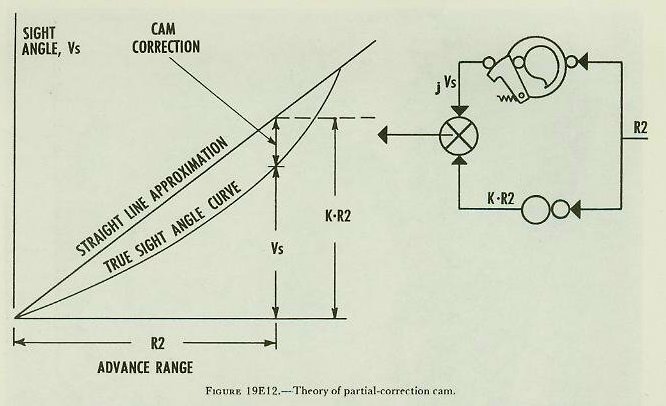
| 19E6. Reducing cam displacement If a cam is cut to supply the full value of a function of a variable, it must necessarily be fairly large to provide accurate outputs. The size of the cam (and thus the ultimate size of the computer itself) can be greatly reduced if it is made to supply only a part of that function. This result can be obtained with the partial-correction cam which makes use of a straight-line approximation. Assuming that it is desired to compute sight angle Vs by a cam, refer to figure 19E12. The true sight-angle curve is plotted in the figure with advance range R2 as the abscissa and sight angle Vs as the ordinate. A sample computation is represented graphically in the figure. At a given advance range R2, the corresponding sight angle Vs can be found from the graph by moving vertically from the value of advance range to the sight-angle curve. However, the actual cam is cut to produce not Vs, but the quantity labeled �cam correction� on the curve, jVs* on the diagram to the right. This correction is the difference between the true sight-angle curve and the straight-line approximation of the curve. Since the straight line has constant slope, its ordinate at any given value of R2 is equal to a constant K times R2 (KR2). This multiplication can be accomplished by a gear ratio, as indicated. The value of KR2 is then combined with the corresponding value of cam correction in a differential, as shown in the figure. The output of this differential will then be the value of Vs for the given R2. In other words, Vs=jVs+KR2. With this arrangement, the size of the cam is greatly reduced. *The symbol j before a quantity, as used here, will be encountered frequently. As defined in the appendix, �Before a quantity it means a correction or partial correction to that quantity, usually generated by the mechanism; after the quantity it means an arbitrary correction (spot) to the quantity.� In mechanical computers, j is used before a quantity with two distinct meanings, first, as in present range (jR), in the sense of an initial or corrective setting and second, as in the present case, the output of the partial-correction cam, where it expresses a partial value of the quantity-a value to which something else must be added to obtain the complete quantity. |
 |
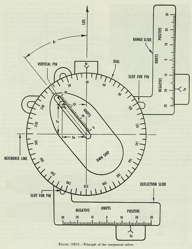 |
| 19E7. Component solvers The component solver is a device for resolving a vector into components with respect to a reference line. In the analytical solution of the fire control problem, it was shown that own ship target, and wind motions are represented by vectors and resolved into components in and across the line of sight. The component solver which resolves own ship�s motion into Yo and Xo is shown in figure 19E13. The dial carrying the compass rose and own-ship outline is free to rotate. The vertical pin may be moved in the radial slot. Two reference lines are shown, the vertical one representing the line of sight. The center of the vertical pin corresponds to the arrowhead of a vector representing the motion of own ship. The distance of the pin from the center of the dial represents own-ship speed (So). The angular position of the radial slot with respect to the line of sight corresponds to relative target bearing. If Br and So are properly set, the displacement of the pin from the reference lines will be a measure of Xo and Yo to the same scale as that used for setting So, as shown in the small triangle. Inspection will show that the component solver solves the equations Xo=So sin Br and Yo=So cos Br. Figure l9E13 shows the arrangement for picking off the outputs. The range slide is mounted so that it moves only parallel to the LOS, while the deflection slide moves perpendicular to the LOS. The vertical pin extends below the dial and fits in the slots of the slides. Thus, as the pin is moved, the slides are driven the amounts shown against the Xo and Yo indices. In the actual computer, the scales are replaced by gear teeth to form racks, meshed with spur gears rotated by the Xo and Yo outputs respectively. |
 |
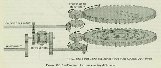 |
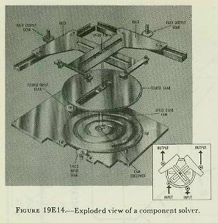
| Component solvers used in computers differ in details but operate according to the same principle. Figure l9El4 shows the type now in general use for resolution of ship, target, and wind motions. The dials indicating the speed and angle setting are on the face of the computer, separated from the actual component solvers but connected by suitable shafts and gears. The position of the course gear determines the direction of the vector with respect to the reference line. The radial position, or speed setting, of the pin is controlled by the spiral groove in the speed gear. When the speed gear is rotated with respect to the course gear, the spiral slot causes the pin to move in or out, setting the proper lengths of the vector representing ship�s speed. When the speed and course gears are rotated together, and the speed setting is unchanged, there is no radial movement of the pin. There is one possible error in a component solver of this design. If the course gear is turned to reset a vector while the speed gear is held stationary, the course-gear slot will cause the pin to move along the cam groove and introduce an incorrect setting of speed. Such errors are prevented by a differential in the cam input line, called a compensating differential, and illustrated in figure l9El5. Course setting drives one side of the differential. Speed setting drives the spider. The other side gear is used as the output to drive the speed gear. If there is no speed input, the spider is held stationary, and the course input drives through the differential to turn the speed gear the same amount as the course gear, thus preventing any change in speed. If there is no motion of the course input, the speed input drives through the spider to turn the speed gear without disturbing the course gear. The differential thus causes the speed gear to be turned by both course and speed inputs, while the course gear is turned only by course inputs, so that correct settings of one can be made without introducing error into the other. |
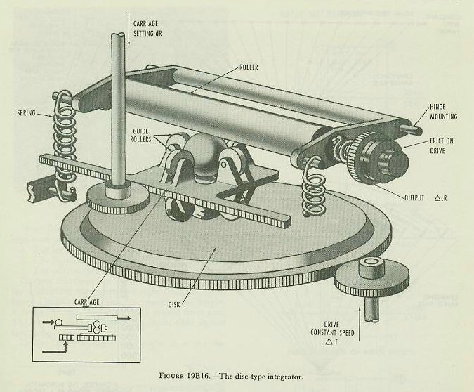 |
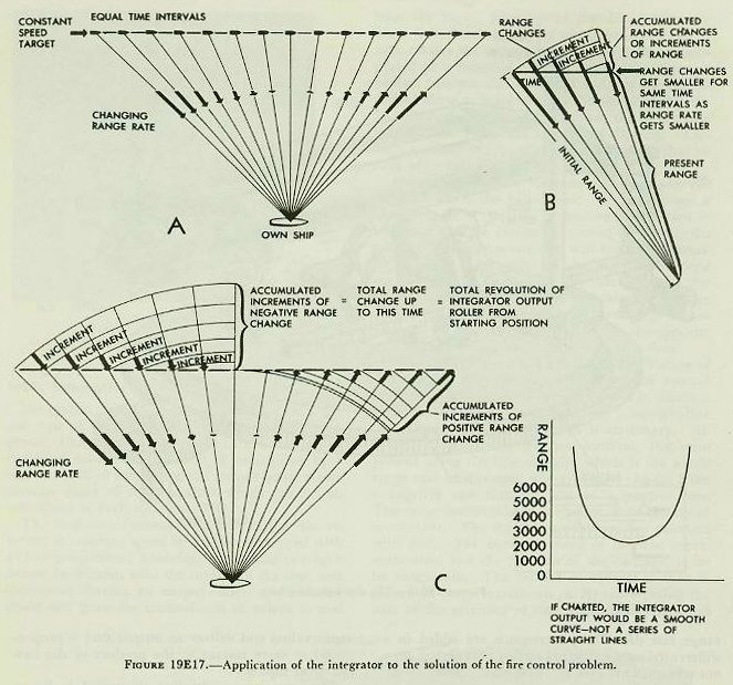
| 19E8. Integrators Integrators, as used in computers, perform a special type of multiplication. In the disc-type integrator, illustrated in figure 19E16, a constantly changing value, such as time, is multiplied by a variable such as range race, the output being a continuous value of their product which can be accumulated as shaft rotation. The instrument consists of a flat circular disc revolved at constant speed by a motor equipped with a clock escapement; a carriage, containing two balls driven by friction with the surface of the disc, and themselves driving an output roller; and suitable shafts and gears for transmission of values to and from the unit. Rotation of the disc rotates the lower ball, which turns the upper ball, and this in turn rotates the output roller. The balls are supported in a movable carriage so that the point of contact between the lower ball and the disc can be shifted along a diameter from the center of the disc to either edge. Spring tension on the roller provides sufficient pressure to prevent slipping. Two balls are used to reduce the sliding friction that results when only one is used. The speed of roller rotation depends upon the speed at which the balls rotate. If the carriage is in the center of the disc, no motion is imparted to the roller. As the carriage is moved off center, the balls will begin to rotate, and will reach their maximum speed at the edge of the disc. The speed varies with the distance of the carriage from the center. Values of rotation on one side of center are considered positive, while if the carriage is moved to the opposite side, rotation will be in the opposite direction and will give negative output values. Figure l9El7 illustrates a practical application of the integrator to the solution of the fire control problem. It shows a simple situation in which a target at constant speed traveling a straight-line course passes own ship, which is stationary. Although target speed remains constant, the component along the line of sight, which is the whole range rate in this case, will gradually change from a negative rate through zero to a positive rate. The range rate continues to change, although speed is constant. The integrator solves such a problem with ease. The constant speed of the disc represents time, and the position of the carriage, is set by range rate. The output of the roller then is generated range increments representing the sum of the products of time increments and range rate dR. These increments are added in a differential to the original setting of observed present range (jR) to give cR, generated present range. |
 |
 |
 |
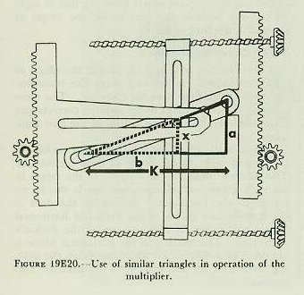 |
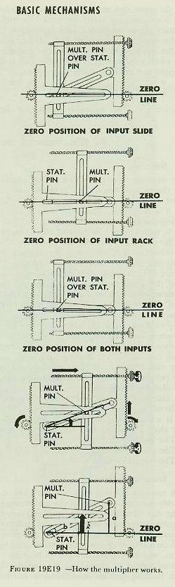
| 19E9. Multipliers In solving a fire control problem it is often necessary to multiply two continually changing values to produce a series of products. This is accomplished by a multiplier. Several types of multipliers are in use, all basing their solutions upon relationships existing between similar triangles. For reasons of space, it is convenient to build multipliers that deliver a fixed fraction of the answer, such as a tenth or a twelfth, rather than the complete numerical value required. The correct answer is supplied by suitable gearing. Multipliers can take two continually changing input values and deliver an output that is proportional at every instant to the product of the two changing inputs. The screw-type multiplier, illustrated in figure 19E18, has two inputs, which position a slide and a rack. The input rack is moved up and down by a spur gear. The input rack moves a slotted pivot arm that pivots around a stationary pin as the input rack is moved. The multiplier pin is mounted in the slots of the input slide and the pivot arm where these slots cross. The position of this pin is changed by movement of the input slide or the input rack. The multiplier pin also fits into a slot in the output rack. As it changes position, the pin moves the output rack up or down. The positions of the input slide and the input rack represent the two values to be multiplied together. The position of the output rack represents the output value, which is always proportional to the product of the two inputs. Suppose the lead screws are turned until the multiplier pin lies directly over the stationary pin. This is the zero position of the input slide, since, with the slide in this position, movement of the input rack will not produce any movement of the output rack. This is shown in figure 19E19. Similarly, if the slot in the pivot arm is positioned parallel to the slot in the output rack, no amount of motion of the input slide can cause any vertical motion of the multiplier pin or of the output rack. This is the zero position of the input rack. Starting with both inputs at their zero position, suppose both input gears turn a few revolutions in the directions indicated. The input slide will move to the right. The input rack will move up its groove, bringing the pivot arm into an angular position. The multiplier pin will be pushed to its new position by the combined action of the pivot arm and the slide. This pin will move the output rack, and the output rack will turn the output gear. Now, labeling the distances each part has traveled from the zero line: 1. The input rack has moved up a. 2. The input slide has moved over b. 3. The output rack has moved up x. If these distances are drawn on the diagram of the multiplier, they form two right triangles, as in figure 19E20. In the smaller triangle, the height, x, is the distance the output rack moved from zero. The base, b, is the distance the input slide moved from zero. In the larger triangle, the height, a, is the distance the input rack moved from zero. The base K is the fixed distance along the zero line from the stationary pin to the pivot on the input rack. Note that the two triangles are similar. It can now be seen that the ratio between the height and the base of the smaller triangle is equal to the ratio between the height and the base of the larger triangle. That is: x/b=a/K. Multiplying both sides by b, bx/b=ba/K. Then, x=ba/K, This equation shows that the distance the output rack has moved from zero is equal to the product of the distances the input slide and rack have moved from zero, divided by a constant. In other words, the output is proportional to the product of the two inputs. Since K is a fixed distance, it is a constant value in each multiplier. Its effect is removed by proper choice of input and output gearing. Provision for both positive and negative x outputs can be made by placing the stationary pin at the center of the pivoted area. |