| NAVAL ORDNANCE AND GUNNERY VOLUME 2, FIRE CONTROL CHAPTER 21 BATTERY ALIGNMENT |
| HOME INDEX Chapter 21 Battery alignment A. Alignment of gun sights B. Train alignment in drydock C. Elevation alignment in drydock D. Battery alignment afloat E. Firing stop mechanisms |
| A. Alignment of Gun Sights 21A1. Introduction No matter how well the elements of a gun battery and fire control system function individually, they cannot function as a system unless they are properly aligned with each other. Battery alignment is the process of aligning all instruments and guns to a common system of reference points, lines, and planes. This process ensures that all associated gun bores, lines of sight and radar beams are parallel when: 1. Dials are matched with correct follow-the-pointer indications, 2. No parallax corrections are made, and 3. No ballistic corrections are made. It ensures further that they remain parallel throughout their operating motions, and that all instrument dials and automatic control equipment measure these motions correctly with respect to the proper reference. The original alignment of a ship’s battery involves (1) the mechanical alignment of the parts making up each element, and (2) the alignment of the various elements with one another. Alignment of parts within an element is largely a matter of design and installation; however, the gunnery officer should be able to check this alignment, and assure himself that it is accurate. Alignment of the various elements with one another is a primary concern of the gunnery officer, who should be familiar with methods employed in effecting the original alignment (in drydock) and should be able to make provision for routine checking and adjustment of the alignment when at sea. The purpose of the train alignment is to adjust the battery so that the lines of sight of directors and guns and axes of gun bores are parallel at all angles of train, when no ballistics or horizontal parallax are considered and the dials are matched. The purpose of alignment in elevation is to adjust the battery so that at any angle of train and elevation the lines of sight of directors and guns and the bore axes will all be elevated at exactly the same angle above a common reference plane, provided that no vertical parallax is introduced, no ballistics are considered, and the dials are matched. This chapter will discuss the alignment procedures employed in drydock and afloat. Under either condition, train alignment is conducted separately from and completed prior to elevation alignment. 21A2. Gun sight alignment Gun sight alignment is that part of battery alignment which involves the mechanical alignment of the parts making up each element, namely, alignment within each mount, turret, or gun of the battery. Gun sight alignment is usually the initial step in battery alignment and consists of three procedures: 1. Boresighting. The pointer’s and trainer’s telescopes do not lie on the axis of the bore. For firing at short ranges in local control they must, therefore, be aligned so that their sighting axes intersect the extension of the bore axis at the target. Since, however, the gun bore is only a few feet from the sights, the error which may be caused by parallel alignment is very small. Thus, for battle use, gun sights may be aligned either to mean battle range for the battery involved or along parallel lines (converging at infinity). 2. Checking for lost motion. The values of sight angle and sight deflection as set on the sights must not contain inaccuracies due to lost motion in the sight mechanism. 3. Checking for parallelism of sights. Sight angle or range settings must elevate or depress the sighting axis of the telescopes in a plane perpendicular to the trunnion axes, and deflection settings must move the sighting axes of the telescopes in a plane parallel to the trunnion axes; in other words the sights must be aligned for parallelism. 21A3. Boresighting The object of boresighting is to make the sight axes and the bore axis converge at either: (1) a specified range, or (2) infinity, with the range scale and the deflection scale reading their zero value in either case. In order to adjust the sights in this manner, use must be made of a boresight telescope. This is a telescope which may be mounted in the bore of a gun and adjusted so that its line of sight coincides with the axis of the bore. Then by sighting through this telescope and through the sight telescopes simultaneously, the latter may be adjusted to obtain convergence or parallelism. There are two main types of boresights: the breech-bar boresight and the boresight with self-contained optics. A breech-bar boresight consists of (1) a boresight telescope, (2) an adapter for installing the telescope in the gun, and (3) muzzle disc used for aligning the telescope on the axis of the bore. With bag-type guns, the adapter takes the form of a breech bar that can be installed across the screw box. A breech-bar boresight can also be used for boresight ing a 5”/38 gun, but with a different type of adapter. The same boresight telescope can be used in boresighting all guns from 5-inch to 16-inch caliber (except the dual-purpose 6”/47 and the rapid-fire 8”/55), if provided with the proper adapters and muzzle discs. Boresights with self-contained optics vary in construction and even in principle of operation, from those that consist merely of a fitting with a small hole for the breech end and another with a pair of cross-wires at the muzzle end, to those that convert the gun into a huge (but low-power) telescope. Self-contained optics boresights are made to fit only the guns for which they are designed. No parts of them are interchangeable between guns. The boresighting process with either major type of boresight is substantially similar, except that breech-bar boresight telescopes must first be aligned on the gun bore axis by sighting on the muzzle disc. This step is not necessary when using boresights with self-contained optics. This section describes boresighting with a breech-bar boresight, which requires this extra operation. |
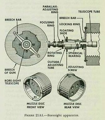 |
| 21A4. Boresight apparatus (breech-bar type) The equipment required at the gun to boresight a bag gun includes, as noted in the preceding article, a breech-bar, a boresight telescope, and a muzzle disc. The equipment and method of mounting on a gun are shown in figure 21A1. The breech bar is a precision-machined bar which can be attached to the face of the breech by two screws. There is a hole through the midsection to receive the outer tube of the boresight telescope. The boresight telescope tube is mounted within an outside adjusting tube which screws into the breech bar and is locked by means of the locking ring. Within the adjusting tube, the telescope is mounted in a spherical bearing which permits the telescope to be adjusted in both the horizontal and the vertical plane by means of four adjusting screws, so that the axis of the telescope can be made to coincide with the axis of the bore. The telescope has three rings near the eyepiece: (1) the reticle focusing ring for focusing the eyepiece to the individual eye, (2) the objective focusing ring for focusing the telescope on the target and eliminating parallax error (apparent target displacement when the eye is shifted about the optical axis of the eyepiece), and (3) the rotating ring, which permits rotation of the telescope about its axis within the outer adjusting tube. |
| The muzzle disc is a circular casting designed to fit snugly in the muzzle of the gun. Through the center of the disc is a small hole, and around it are four larger holes, arranged as shown in figure 2lAl. Etched rings around the edge of the disc provide means for fitting the disc in the muzzle perpendicular to the axis of the bore. Notches are engraved on both disc and gun as index marks. With these index marks matched, one row of holes is aligned vertically and the other horizontally with respect to the gun. The purpose of the disc is merely to assist in the alignment of the boresight telescope axis with the bore axis. Once aligned, the muzzle disc is removed and has no further part in the boresighting of the gun until the final stage, when it is remounted for a recheck of alignment to assure that no error has crept in during the process. Boresights with self-contained optics do not require the use of a muzzle disc in obtaining alignment with the bore axis. 21A5. Boresighting preparation The general steps necessary in getting the gun ready for boresighting arc as follows: 1. See that pointer’s and trainer’s scopes are clear, focused, and free from parallax. 2. Remove all evident lost motion from the sight mechanism. (See article 21A8.) 3. Lash back the breech plug so that motion of the ship will not swing the plug against the bore-sight apparatus. (For case guns, make sure that the breechblock is securely held down.) 4. Install breech bar, boresight telescope, and muzzle disc. (For boresights with self-contained optics, only the boresight components are installed. No muzzle disc or breech bar is required. Steps 5 and 6 below are also unnecessary, as is the final step in article 21A9.) 5. Focus the boresight telescope and center the crosshairs on the small center hole in the muzzle disc, using the four outer holes to align the cross-hairs vertically and horizontally. 6. Remove the muzzle disc. 7. Set the range scale at zero (sight angle scale set at its zero value-usually 2,000 MIN) and deflection scale at the midpoint (usually 500 mils). 21A6. Choosing a target A target with a clearly defined and visible point is suitable for boresighting in both deflection (train) and elevation. In the absence of such a target, two targets may be used: one with a clear vertical line for boresighting in deflection, and one with a clear horizontal line in elevation. If the guns are being readied for a specific gunnery practice, the target selected should be at the range specified for that practice. For general use a target should be chosen at about the range at which the guns being boresighted are most effective, called the mean battle range. Or, if a parallel alignment is desired, a distant target like a star may he chosen. For elevation only, the horizon often makes an excellent target, especially for such guns as the 5-inch and 6-inch, for which it roughly corresponds to mean battle range. |
 |
 |
 |
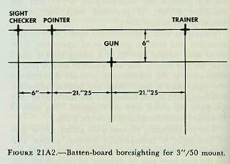
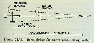
| 21A7. Batten-board method When a suitable target is not available, as often happens in drydock, or when it is necessary to bore-sight during rough or foggy weather, the batten-board method is used. It can be used either to set the sights exactly parallel to the axis of the bore, or to attain any desired angle of convergence. A batten board is a screen set vertically on deck at any convenient distance normal to the bore axis of the gun. Marked on the batten are vertical and horizontal lines spaced at exactly the same distances that the telescopes are spaced from the gun bore(s)-these distances can be found in the Ordnance Pamphlet for the mount or turret. The markings on a batten for the 3”/50 pedestal mount are shown in figure 2lA2. If boresighting for a specified range, the separation of the lines on the batten board should be reduced. The required spacing can be readily calculated by the principle of similar triangles, as is shown in figure 21A3. 21A8. Looseness of parts and lost motion Before beginning the actual boresighting, check for looseness of parts and for lost motion in the sight mechanism. To check for looseness of parts, first sight on some convenient target. Then manually shake all adjustable parts, and recheck the crosshairs on the target. If the sights are off, tighten the linkage and try again. This check should be performed independently for the trainer’s and pointer’s telescopes. |
| To check the sight mechanism for lost motion, set the sights so that the crosshairs are on a target whose position with respect to the gun remains fixed. Use a point on the ship itself or, if the ship is in drydock, a target outside the ship. (If the target is close to the mount, some means of removing telescope parallax, such as a focusing cap, may be required.) While this check is going on, keep the gun stationary. Set the sights at maximum range on the range scale and then return them to their original setting. If there is no lost motion, the horizontal crosshair will return to its exact position on the target. Make a similar check for the vertical crosshair by setting maximum sight deflection, returning to original deflection setting, and observing change due to lost motion, if any. If there is lost motion in the sight mechanism, it can be removed by taking up excessive play or clearance between moving parts. 21A9. Boresighting the gun To boresight in train, bring the gun to bear on the target so that the vertical crosshair of the bore-sight telescope is aligned with a vertical mark on the target. When the boresight is on, the man at the boresight calls “Mark.” If the pointer’s and trainer’s vertical crosshairs are not on target, adjust them until all vertical crosshairs are on at “Mark.” Similarly, to boresight in elevation, align the horizontal crosshair of the boresight telescope with a horizontal mark on the target. The sight checker’s telescope should also be adjusted in both deflection and elevation. After boresighting, recheck for looseness of parts. Before securing, place the muzzle disc in the gun to make sure that the boresight line of sight is still coincident with the axis of the bore. If it is not, boresighting must be repeated. 21A10. Checking parallelism of sights The check for parallelism is usually made while in a naval shipyard. Shipyards usually have available permanently constructed battens, similar to those used for boresighting but with the lines somewhat longer than necessary for boresighting only. Secure the gun in train; install and adjust the boresight; and set the sight scales at zero range (no sight angle) and no deflection. Mark the points near the bottom of the batten where the lines from the boresight and the gun-sight telescopes appear to intersect the surface of the batten board (three separate points). Next, elevate the guns and mark a point near the top of the batten where the line of sight from the boresight telescope intersects the batten. The upper and lower points for the gun determine the elevation line of the gun; run a fine piano wire between the pair of points to represent this line. From the lower points established by the pointer’s and trainer’s telescopes, mark off sight lines by stringing piano wires parallel to the elevation line of the gun. |
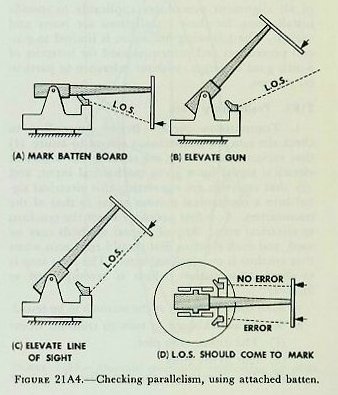
| With the gun elevated near the top of the batten, the vertical crosshairs of the pointer’s and trainer’s telescopes should, when range is set on the sights, move down along their respective sight lines on the battens. If they do not, the sights and gun do not elevate in parallel planes. To make a similar test ‘for parallelism of the motion of the sight in azimuth with the boresight, spot in points on a batten as the gun is trained to establish the gun-train line. Draw a second line parallel to the gun-train line at the level of the sights. This sight-train line must be located on the same level as the sights to be checked, to keep the sight plane horizontal; otherwise, when deflection is set, the LOS will fail to follow the horizontal line, even though the sights are in correct adjustment. To complete the check, set deflection into the sight mechanism. As deflection settings are varied, the lines of sight of the telescopes should follow the sight-train line established on the batten. For gun mounts with carriage-type gun sights an easier method of checking for parallelism utilizes a small batten board attached to the gun muzzle(s) (see fig. 21A4). With this board attached, start with the gun near zero elevation. Depress the sights by setting in some sight angle, and mark the points on the board where the lines of sight of each telescope meet it. Now elevate the gun. This will cause the lines of sight to move off the marks. If the sight trunnions and the gun trunnions are truly parallel, it should be possible to bring the lines of sight back on the marks by use of the sight-angle crank only. If there is an error, it can be measured by using the sight-deflection adjustment to get back on the marks. |