US NAVY
FIRE CONTROL PAGES
NAVAL ORDNANCE AND GUNNERY
VOLUME 2, FIRE CONTROL
CHAPTER 24
ANTIAIRCRAFT PROBLEM
ANALYTICAL
Chapter 24 Antiaircraft problem analytical
A. Target positioning
B. Ballistic computations
C. Gun positioning
24A1. Introduction
The antiaircraft fire control problem requires computations for its solutions which, although more complex, are in many respects similar to those already considered in the surface problem. The same basic fire control problem must be solved, namely: present target position must be continuously determined; ballistic corrections, whereby the axis of the gun bore is offset from the LOS, must be computed; motion of gun platform must be corrected for; gun orders must be made up; and provisions must be made for correcting an inaccurate solution.
The air problem is more complicated than the surface problem because, as a result of target elevation (E), it is three-dimensional; it may require the use of time-fuzed projectiles; and the problem develops with much greater rapidity due to higher target speeds.
In order to simplify the presentation, certain factors in the analytical solution are described in a manner which does not exactly agree with the process carried out by a computer. For reasons of space and weight limitations, the automatic solution includes empirical expressions and mathematical short cuts which are not here discussed, as they do not contribute to the understanding of the analytical solution of the AA problem.
In this chapter the line extending from the gun to the advance target position is called the line of fire (LOF). The vertical plane containing the LOF is called the plane of fire. The actual flight of the projectile is from the own-ship position to the advance target position. In the surface problem ballistics were based on the LOS, while in the AA problem the change in target position during time of flight (Tf) of the projectile is of sufficient importance to warrant computing ballistics on the basis of the LOF. This section of the chapter deals with target position in the solution of the AA problem. Subsequent sections will take up ballistic computations and gun positioning.
24A2. Target position in relation to time
In considering target positioning, it should be noted that we are actually concerned with the target’s position at three distinct times: (1) The present target position, (2) the target position at any given instant (generated target position), and (3) the target position at the end of a specific time (advance target position), this specific time being Tf.
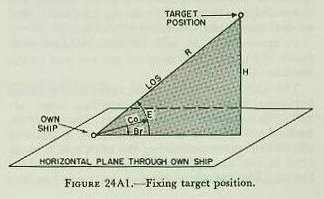
In the analytical solution, target position with respect to own ship is fixed by use of three coordinates: Present range (R), relative target bearing (Br), and target elevation (E). These quantities are illustrated in figure 24A1, and are defined as follows:
R Present range. The distance of target from own ship measured along the LOS.
Br Relative target bearing. The horizontal angle between the vertical plane containing the fore-and-aft axis of own ship and the vertical plane containing the LOS, measured clockwise from bow of own ship.
Br and E can be determined by measuring the position of the LOS, while R can be measured by rangefinder or radar. As there is likely to be motion of own ship and target, successive instantaneous positions may be established by continuing to direct the LOS at the target and by measuring the present range.
24A4. Generated target position
In the equipment under discussion, present relative target position is generated by rangekeeper methods similar to those employed in the surface fire control problem. Generated relative target position is then used as the basis of the solution for sight angle (Vs), sight deflection (Ds), and fuze-setting order (F).
The generated target position can be expressed by the following equations:
cR=jR+increments T (dR) =jR+increments cR.
cBr=jBr+increments T (dBr) =jBr+increments cBr.
cE=jE+increments T (dE) =jE+increments cE.
The initial values of R, Br, and E are obtained by measurement. Increments of time (increments T) can also be considered as a measured quantity. This leaves the three rates, range rate (dR), angular bearing rate (dBr), and the angular elevation rate (dE) to be determined. This is done in two steps:
1. Resolve own ship’s motion into horizontal components and target’s motion into horizontal and vertical components of relative target motion.
2. Then resolve these horizontal and vertical components into three rates dR, dBs, and dE with respect to the LOS.
Resolution of own ship’s motion is accomplished exactly as in the surface problem. Ship’s motion is in the horizontal plane. Aircraft target motion cannot be resolved entirely into the horizontal plane, as the target may be climbing or diving.
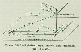
In figure 24A2 the vector representing target motion is labeled S, is with respect to the earth, and is resolved into two components, horizontal target speed (Sh) and vertical target speed (dH), (called rate of climb and would be negative if target is descending). Sh and dH are the horizontal and vertical components, respectively, of S.
In figure 24A3, Sh and dH are combined with figure 24A1, and these motions are resolved in the horizontal.
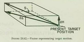
dRh=Yo+Yt=So cos Br+Sh cos A.
RdBs=Xo+Xt=So sin Br+Sh sin A.
The algebraic sign of the components can best be determined by inspection of a diagram of any particular problem. A component that tends to increase the basic coordinate is considered positive.
As yet the solution for present rates is incomplete. Direct range rate is defined as the rate of change of range along the LOS. Horizontal range rate (dRh) is not the same as direct range rate (dR), since it is not measured along the LOS. The change of bearing has to be converted to an angular rate of change which may be applied directly to initial bearing. A solution for elevation rate (RdE) must be developed, and it must also be converted to an angular rate. The completion of the solution with applicable formulas follows:
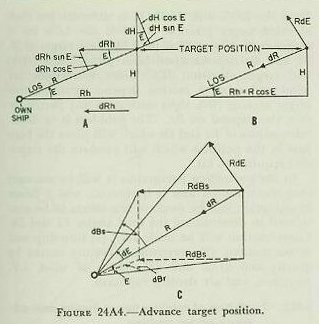
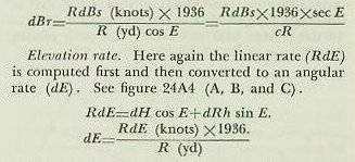
Range rate. Both dRh and dH are in the vertical plane through the LOS and are inclined to it by E and (90°-E) respectively. By inspection of figure 24A1, it can be seen that direct range rate Is made up by resolving dRh and dH with respect to theLOS, or, by referring to figure 24A4 (A and B), it can be seen that
dR=dH sin E+dRh cos E.
Angular rate (minutes of arc/sec)=linear rate (knots) X 2027/3600 (yd/sec) X l000/R (yd) (to obtain angular rate in mils)X3.44 (minutes of arc/mil.
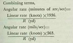
In a rangekeeper or computer it is more convenient to multiply by the reciprocal of the cosine (1/cos=sec) than to divide by the cosine itself. The mark lA computer was designed to use generated present range (cR) instead of observed present range, because at the time of design rangefinder ranges had to be used. Rangefinder ranging is necessarily intermittent. Continuous radar ranges of satisfactory quality are now available and are often introduced indirectly into the computing mechanisms by keeping the generated values equal to the observed.
The present rates of relative target motion dR, dBr, and dE serve another purpose. Based on the assumption that these rates will remain constant for short periods of time, these present rates can be used to predict the target’s position at the end of time of flight (Tf) of the projectile. The results may be considered as determining an approximate line of fire. As previously mentioned, this LOF, because of high speed of the target, may be considerably different from the LOS. Ballistic computations are based on this LOF.