US NAVY
FIRE CONTROL PAGES
NAVAL ORDNANCE AND GUNNERY
VOLUME 2, FIRE CONTROL
CHAPTER 25
LINEAR-RATE ANTIAIRCRAFT
FIRE CONTROL SYSTEMS
Chapter 25 Linear-rate antiaircraft fire control systems
A. General description
B. Director
C. Computer
D. Mark 6 stable element
25D1. Introduction
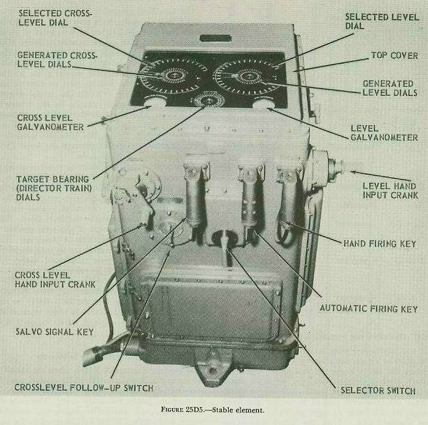
The Mark 6 stable element (fig. 25D5) is one of the three major units of the Mark 37 gun fire control system. It is located in the plotting room adjacent to the Mark 1A computer, as shown in figure 25C2. In general, the primary function of the Mark 6 stable element is equivalent to that of the stable vertical in the main-battery system; that is, it measures level angle (L) and crosslevel angle (Zd)- angles caused by the variation of the position of the deck of the ship with respect to the horizontal and hence required in the solution of the fire control problem. As will be explained in subsequent articles, the stable element accomplishes this function by using a gyroscope to establish the true vertical and its associated true horizontal plane.
25D2. Gyroscopic principles
As explained in article 19G2, a gyroscope has two properties that make it useful in fire control. These properties are gyroscopic inertia, and precession. Because of its inertia, a spinning gyro tends to keep its axis pointed in a fixed direction in space. Because of precession, it tends to tilt its axis in a direction at right angles to that of any force applied to it.
Solution of the fire control problem requires that we know the true vertical and horizontal, so that the level angle (L) and crosslevel angle (Zd) can be measured. In the Mark 6 stable element, the righting system makes the gyro axis assume and maintain a true vertical position. This system has two principal parts: the mercury control system and the latitude correction system.
Mercury control system. This system introduces a righting force which causes the gyro spin axis to precess to the vertical and, in addition, counteracts the effects of friction, acceleration forces, shocks, and other disturbances which would tend to displace the spin axis from the vertical.
Essentially the mercury control system consists of two tanks containing mercury, attached to the casing which houses the gyro wheel, on diametrically opposite sides of the wheel. These two tanks are joined by two narrow connecting tubes as shown in figure 19G4. The top tube is merely an air-pressure equalizing connection between the two tanks. The lower tube permits the free flow of mercury from either tank to the other. As long as the gyro wheel is exactly horizontal, the mercury level in both tanks will be the same; but as soon as the wheel is tilted from the horizontal by some external force, gravity will cause mercury to flow from the high tank to the low tank. The additional mercury in the low tank will then produce the same effect as a downward pressure exerted at the low point of the gyro wheel.
Application of the rule of precession shows that this will only cause the wheel to precess more out of the horizontal in a direction 90° away. However, if the mercury effect is applied not at the low point but 90° from the low point, pressure at this point will cause the low point of the gyro to precess upward to its original horizontal position, at which point the mercury is redistributed equally.
This effect is accomplished in the stable element (1) by a gimbal rotation motor which rotates the entire gyro assembly and attached mercury tanks at 18 rpm in the same direction as gyro spin, and (2) by installation of an orifice to regulate the flow of mercury in the lower connecting tube. The net result is that, by the time the mercury has reached the low tank, the low tank has been displaced 90° from the low point of the gyro wheel, and the pressure exerted here causes the gyro spin axis to precess back into the vertical. This, moreover, is exactly what takes place when the gyro is first started. As a result of mercury flow and gimbal rotation, the gyro spin axis automatically erects itself and settles in the vertical after several minutes of operation.
At times certain irregularities of ship motion, such as sharp turns or speed changes, occur which cause an irregular flow of mercury, tending (as the result of either centrifugal force or inertia) to displace the gyro spin axis from the vertical rather than to right it. To prevent mercury flow at such times, a mercury cut-out valve closes, thus blocking the lower connecting tube. This valve is operated automatically by a cut-out control on the stable element’s control panel.
Latitude correction system. It was shown above that the mercury control system brings the spin axis of the gyro to the vertical. However, effective operation of that system depends upon a definite displacement of the spin axis from the vertical. Consequently, if the mercury control system were to act alone, the gyro spin axis still would deviate slightly from the vertical as a result of the apparent tilt caused by the earth’s rotation. In other words, the spin axis would be continuously lagging, but attempting to regain, its vertical position.
On the other hand, a gyro located at the equator will assume the successive positions with respect to the earth shown in the left-hand illustration. To an observer standing on the earth, the wheel will appear to turn completely over every 12 hours; that is, to turn backward (toward the west) with respect to the earth’s rotation at the rate of one revolution every 24 hours.
At any point between the pole and the equator, as shown in the center and right-hand illustrations, the gyro wheel will appear to gyrate once every 24 hours about an axis parallel to the axis of the earth’s rotation and in a direction opposite to that of the earth’s rotation. This effect can be compensated for if the gyro can be made to precess slowly to the eastward at the same rate as the earth’s rotation. The gyro’s plane of rotation will then remain parallel to the horizontal plane.
This is accomplished in the stable element by means of a latitude correction system which consists essentially of a latitude weight and a latitude motor. The latitude weight is so arranged as to cause a downward pressure at the north point of the gyro wheel, resulting in an easterly precession. The position of the latitude weight is adjustable, so that the weight can be set for the latitude in which the ship is operating. Usually it is considered sufficient to make a latitude setting once a day.
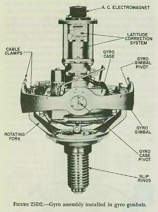
To ensure that the latitude weight remains properly oriented in a northerly direction so as to cause easterly precession of the gyro, certain factors must be taken into consideration. The latitude weight, as shown in figure 25D2, is mounted at the upper end of the gyro assembly. The gyro assembly, however, does not remain stationary. It turns with the ship (in a horizontal sense) during a change of course (Co); it is rotated by director train (B’r), as will be explained in a subsequent article, to permit proper measurement of level angle (L) and cross-level angle (Zd); and, finally, it revolves at 18 rpm to permit proper operation of the mercury control system as previously pointed out. Obviously then, provision must be made to cancel out the effects of Co, B’r, and 18 rpm if the latitude weight is to re main in a northerly direction.
This is done in the stable element by a synchro known as the latitude motor. The rotor of this motor supports the latitude weight, and the stator is attached to the gyro case. The electrical input to the motor positions the rotor with respect to the stator. Consequently this input must be the sum of ownship course (Go), training gear rotation (B’r), and gimbal rotation (18 rpm) if the latitude weight is to remain properly oriented.
Two differential generators, which, in effect, are electrical differentials, are employed to make up this electrical input to the latitude motor. As illustrated schematically in figure 25D6, input Co goes to the director train differential (mounted in the base of the instrument) where B’r is added to it. The sum, Co+B’r, goes to the gimbal rotation differential (mounted on the level frame). There 18 rpm is continuously added to Co+B’r. The output to the latitude motor stator, Co+B’r+ 18 rpm, holds the latitude motor’s rotor stationary with the weight in a northerly direction-the 18 rpm effectively stopping the rotor on the LOS, B’r effectively bringing the rotor to the fore-and-aft axis of the ship, and Co orienting the rotor to North.
25D4. Mechanical construction
The Mark 6 stable element, like the stable vertical used in the main-battery fire control system, consists essentially of a sensitive element and a measuring group.
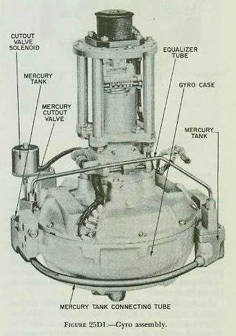
Sensitive element This is the heart of the instrument and consists of the gyro, gyro case, gyro gimbal, and a fork-shaped support known as the rotating fork. Figures 25D1 and 25D2 illustrate these parts in the stable vertical’s sensitive element. Corresponding parts in the stable element are essentially the same.
Figure 25D1 shows the gyro proper. The wheel is carried on an axle supported by ball bearings at the upper and lower ends of the gyro case, the wheel and case forming the rotor and stator respectively of a high-frequency induction motor. A squirrel-cage winding, consisting of solid conducting bars, is in the gyro wheel, while wire stator windings are in the gyro case. A special motor-generator is provided to supply power at a frequency sufficient to drive the gyro at about 8,500 revolutions per minute.
The gyro assembly of figure 25D1 pivots within the gyro gimbal on a case axis perpendicular to the spin axis, as shown in figure 25D2. The gyro gimbal, in turn, is supported by the arm of the rotating fork on the gimbal axis, which is perpendicular to both the case axis and the spin axis. This axis arrangement provides a universal mounting giving the gyro three degrees of freedom, and allows it to spin on a vertical axis, even though the rotating fork may vary its position from time to time.
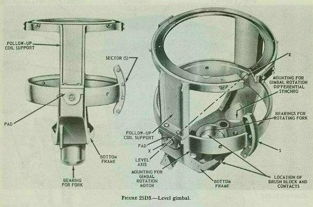
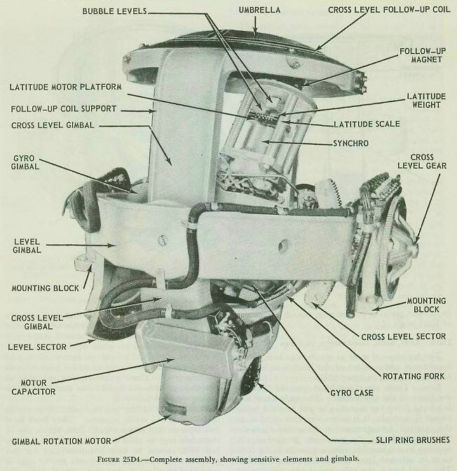
Measuring group. This consists of a level gimbal, a crosslevel gimbal, training gear, and as will be described more in detail in a subsequent article, an umbrella and its follow-up coils. Figures 25D3 and 25D4 illustrate the stable vertical’s measuring group. The measuring group of the stable element is not entirely the same. The important difference lies in the manner in which level angle (L) and crosslevel angle (Zd) are measured. In the stable element, the outer gimbal is the crosslevel gimbal, supported at its trunnion bearings by the training gear structure (main frame). The outer (crosslevel) gimbal, in turn, supports the inner or level gimbal so that the gimbal axes are mutually perpendicular. It can be seen from this gimbal relationship that, in the stable element, L is measured in a vertical plane while Zd is measured in a plane perpendicular to the deck. This is just the reverse of the measurement of level and crosslevel angles in the stable vertical.
At the lower end of the inner (level) gimbal there is a bearing for the rotating fork. The entire sensitive-element assembly of figure 25D2 is mounted within the measuring-gimbal system of figure 25D3, being supported at its lower end by the rotating fork in this fork bearing, so that it is free to rotate within the measuring group. The complete assembly is shown in figure 25D4. A gimbal rotation motor, attached to the lower end of the inner (level) gimbal, is geared to the rotating fork and drives it at 18 rpm. The fork turns the entire sensitive element at this speed within the measuring-gimbal system. This rotation is essential to the mercury control system as explained in article 25D3.
The actual measurement of level angle (L) and crosslevel angle (Zd) in the stable element is similar to the measurement of comparable angles in the stable vertical, and is accomplished by a follow-up system. This system centers about an electromagnet, called a follow-up magnet, and two follow-up coils.
The umbrella is attached to and moves with the top of the level gimbal. It contains two follow-up coils. The level follow-up coil is imbedded in grooves on the upper side of the umbrella, while the crosslevel follow-up coil is similarly carried on the underside. In effect, each coil is wound in the shape of a figure eight, the turns being clockwise in one loop and counterclockwise in the other.
The line joining the loop centers of the level coil is at right angles to the level axis, which means that it lies in the vertical plane through the LOS when the training gear is oriented by B’r. The corresponding line of the crosslevel coil is at a right angle to the crosslevel axis, and therefore lies across the vertical plane through the LOS. The center of each figure-eight coil is on the umbrella center.
The follow-up magnet is mounted on top of the gyro case, as shown in figure 25D2, so that its axis coincides with the spin axis. The magnet is energized with alternating current which sets up an alternating magnetic field. This field induces voltages in the follow-up coils. The action of the crosslevel follow-up is the same as that of the level follow-up; hence the rest of this discussion is confined to the level system.
When the umbrella center is on the spin axis, the voltages induced in the two loops of the level coil are equal in magnitude. Since the loops are wound in opposite directions, their voltages at any instant, however, have opposite polarity, and their resultant voltage is zero. When a change in level angle occurs (during rolling or pitching of the ship), the umbrella, which tends to follow the ship, moves off the spin axis in the vertical plane through the LOS. The follow-up magnet, however, remains in the vertical because of the action of the gyro. Consequently, the magnet is then closer to one loop of the level follow-up coil than to the other, and induces a higher voltage in the first loop than in the second.
The resultant voltage across the coil is no longer zero, but has both magnitude and direction which provide an indication of the follow-up action required. The amount that a follow-up must drive automatically or that a handcrank must be turned manually to reposition the level gimbal in the horizontal plane-and hence to return the umbrella to its neutral position on the spin axis-is a measure of level angle (L).
The locations of most of the various keys, dials, handcranks and switches of the Mark 6 stable element can be seen in figure 25D5.
Keys. There are three hand-operated keys on the front of the instrument. The right-hand key is a hand firing key that may be put into the firing circuit if desired. It is in no way connected with the internal arrangement of the stable element. The middle key is the automatic firing key. It operates in conjunction with automatic firing contacts in selected level or selected crosslevel fire. The third key is the salvo-signal key. It is used to sound buzzers in the mounts as a warning just before the firing circuit is closed.
Dials. There are three sets of dials under the square window at the top of the instrument. The pair of concentric dials at the front and center indicate the fine and coarse values of director train B’r against a fixed index. The two remaining sets of dials each consist of a trio of concentric dials. The inner and intermediate dials respectively indicate fine and coarse generated values against a fixed index. The outer ring dial indicates the selected value against the same index when selected values are being used. The right-hand set of dials registers values of level, while the left-hand set indicates crosslevel. Two galvanometers are located on the top of the instrument, one for level and one for crosslevel. These galvanometers are used in conjunction with the handcranks described below during manual follow-up.
Handcranks. There are two hand-input cranks installed on the stable element. They both have two separate and distinct uses. First, either one or the other may be used to put in a selected value, but both cannot be used simultaneously for this purpose. Secondly, the handcranks can be used in manual follow-up, a procedure which was mentioned in article 25D5 and which will be explained in detail in a subsequent article.
Neither handcrank can simultaneously accomplish both uses. If, for example, the level hand-crank were constantly being rotated for manual follow-up in level (to keep the level follow-up coils centered over the follow-up magnet), it could not concurrently be used to set in a selected value of level. Both handcranks are either engaged or disengaged by magnetic clutches which are controlled by the selector and follow-up switches described below.
Switches. Three switches are installed on the stable element for its control. They are: the selector switch, the crosslevel follow-up switch, and the level follow-up switch. The first two can be seen on the front of the instrument in figure 25D5. The third is located to the right of the level hand-input crank on the right side of the instrument.
The selector switch is used in selecting the type of fire desired. It has three positions labeled LEVEL FIRE, CONTINUOUS FIRE, and CROSSLEVEL FIRE.
When the selector switch is thrown to a selected type of fire (for instance, level or crosslevel), it causes the corresponding handcrank to become engaged.
The two follow-up switches, which are identical in operation, control the method of follow-up used.
Each has two labeled positions, AUTOMATIC and MANUAL. The switches have nothing to do with the type of fire used but, if a switch is on MANUAL, its corresponding handcrank, already being used for manual follow-up, cannot be used for selected fire. For example, if the level follow-up switch were on MANUAL, selected-level fire could not be used but crosslevel fire could be used; therefore, in this particular instance, the selector switch would have to be on either CONTINUOUS FIRE or CROSSLEVEL FIRE.
The inputs and outputs of the Mark 6 stable element are summarized below, together with their more important uses. Most of them have been discussed previously, either in the preceding articles or in the study of the Mark lA computer and the Mark 37 director.
It should be noted that all outputs to and inputs from the computer, listed above, are transmitted mechanically by shafting. On the other hand, Co and the value of Zd sent to the director are both electrically transmitted.
Inputs
Quantity......................Received from............Used
1. B’r..........................Computer................... To assist in making up L and Zd; to orient gimbals to LOS; to orient latitude weight to North.
2. Co...........................Gyro compass............ To orient latitude weight to North.
3. Own ships latitude...Set manually.............. To counteract for earth’s rotation effect on gyro.
4. Lj or Zdj..................Set manually.............. In selected fire.
Outputs
1. Zd...........................Director..................... To stabilize optics and radar antennas.
2. Zd or Zdj.................Computer................... To compute Br from B’r; to compute trunnion-tilt correction.
3. L or Lj.....................Computer................... To compute E from Eb, Br from B’r and trunnion-tilt correction.
4. L + Zd/30................Computer................... To make up elevation correction.
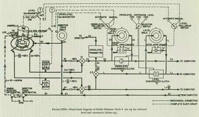
It was mentioned previously that director train (B’r) actually rotates the training gear in the stable element and hence keeps the axis of the crosslevel (outer) gimbal oriented in the vertical plane through the LOS. This is shown in figure 25D6. Within the crosslevel gimbal is carried the level gimbal, its axis being at right angles to the cross-level gimbal’s axis. Thus the input if director train (B’r) positions both gimbals so that level angle (L) is measured in the vertical plane through the LOS and crosslevel angle (Zd) in a plane at right angles to both the vertical plane through the LOS and the deck plane. The quantity B’r, in addition, has other uses. It drives the director train dials on top of the stable element; it assists in holding the latitude weight in a northerly direction as explained in article 25D3; and finally, it is used in determining crosslevel angle (Zd) and level angle plus crosslevel function (L + Zd/30) as will be explained in a subsequent article.
25D9. Gear walking
The crosslevel gimbal is connected to the cross-level follow-up motor by a gear train and shafting which may be driven either by the motor or by the crosslevel handcrank as can be seen in figure 25D6. The drive passes through the training gear. When the latter turns, a pinion in the gear train “walks” on another gear in a manner similar to the walking of the pinion on the floating gear in director telescopes. This walking is a function of the director train, f(B’r), similar in nature to the crosslevel function Zd/30. The follow-up motor (or hand-crank) must therefore supply the quantity Zd + f (B’r) to the shaft driving the crosslevel gimbal, in order to move the gimbal through the angle Zd to its original horizontal position.
The level gearing is similar in many respects to the crosslevel gearing. However, in addition to passing through the training gear it also has to pass through the crosslevel gimbal to reach the level gimbal. Consequently, crosslevel gimbal motion causes walking of a pinion in the level drive. This gear walking causes motion of the level gimbal in an amount equal to a function of crosslevel. This motion must be compensated for by rotation of the level shafting. The gear ratio used makes this function equal to Zd/30 to match the function required at the director telescopes. The level follow-up motor (or the level handcrank) must therefore supply the quantity L + Zd/30 + f(B’r) to the shaft driving the level gimbal in order to move the gimbal through the angle L to its original horizontal position.
25D10. Operation: automatic follow-up
As explained in article 25D5, when the center of the umbrella moves away from its neutral position over the follow-up magnet, a voltage is induced in at least one of the follow-up coils. The only difference between automatic follow-up, described herein, and manual follow-up presented in the next article, is the manner in which this follow-up coil voltage is employed. For example, when the level follow-up switch is set on AUTOMATIC, it connects the level coil to the level follow-up units on the control and follow-up panel.
At the panel, the coil voltage is amplified and used to control rectifier tubes which supply direct current to the level follow-up motor. The direction of the current flow determines the direction of motor rotation. The current is applied so that the motor drives the level ring in a direction that will place the umbrella center back on the spin axis. The amount that the level follow-up motor will drive, of course, as explained in article 25D9 and as shown in figure 25D6, is the quantity L + Zd/30 + f(B’r).
The response is made sufficiently sensitive to cause the umbrella center to remain very nearly in line with the magnet. In other words, the follow-up motor functions practically as soon as displacement begins, so that the generation or measurement of L is continuous. If the motor were permitted to drive until the signal voltage became zero, of course, it would coast, as a result of its inertia, and actually drive the level gimbal and the umbrella slightly beyond their neutral positions (in the horizontal plane and on the spin axis, respectively).
Then the follow-up control would operate to run the motor in the reverse direction, and it again would coast beyond the desired position. To prevent this action, which is called “hunting”, an anti-hunt unit is included in the controls at the panel. It operates to shut off the power slightly before the neutral position is reached. A sensitivity control permits adjustment of this action to suit the requirements of individual ships.
Automatic follow-up in crosslevel is accomplished in the same way as in level; that is, the crosslevel follow-up switch is placed on AUTOMATIC, and the crosslevel follow-up motor drives an amount equal to Zd + f(B’r) to return the umbrella to its neutral position.
25D11. Operation: manual follow-up
Automatic follow-up normally is used in the operation of the stable element. However, in case of failure, one or both of the automatic follow-up systems can be replaced by manual follow-up. For example, if the level follow-up motor is inoperative, manual follow-up in level can be used to keep the umbrella centered on the spin axis and thus to ensure the proper measurement of level angle (L). To accomplish manual follow-up in level, the level follow-up switch is set on MANUAL. This setting does three things: It connects the level follow-up coil directly to the level galvanometer; it breaks the armature field circuit of the level follow-up motor, thus causing the motor to idle; and it causes the level handcrank clutch, labeled D in figure 25D6, to become engaged.
Any voltage applied to the galvanometer displaces its needle from the zero position, the amount of the displacement being a measure of level and the direction indicating the required direction of handcrank rotation. When the needle is displaced, the level handcrank must be turned until the needle once again is at zero. This rotation of the hand-crank, in effect, performs the same function as that of the level follow-up motor during automatic follow-up; that is, by driving back through the level-synchronized clutch A and differentials D-2 and D-3 of figure 25D6, it supplies the quantity
L + Zd/30 + f(B’r) to the shaft driving the level gimbal and hence returns the umbrella to its neutral or zero-voltage position.
Manual follow-up in crosslevel is accomplished in a similar way. The crosslevel follow-up switch is set on MANUAL; the crosslevel handcrank clutch C is engaged; and the handcrank rotation drives back through the crosslevel-synchronized clutch B and differential D-1 to supply the quantity Zd +f (B’r) to the shaft driving the crosslevel gimbal.
25D12. Operation: continuous-aim fire
The Mark 37 system was designed for continuous-aim fire, and it is so used most of the time, usually with automatic follow-up at the stable element in both level and crosslevel. Manual follow-up can be used, as explained in article 25D10, but ordinarily is considered a standby measure.
In continuous-aim fire, the selector switch is set at the CONTINUOUS FIRE position, and the two follow-up switches at either AUTOMATIC or MANUAL. Values of L, Zd, and L + Zd/30 are transmitted to the computer, and Zd to the director. Before seeing how these values are transmitted, however, it is essential that the control of the four clutches shown in figure 25D6 be understood. There are two different types of clutches: two synchronized clutches, labeled A and B, and two handcrânk clutches, which are magnetic clutches, labeled C and D.
Selector switch control of clutches. The selector switch controls all four of the clutches shown in figure 25D6-the handcrank clutches electrically and the synchronized clutches mechanically. It is relatively simple to remember when these clutches are either engaged or disengaged if certain stable-element operating conditions are considered as “normal”. As pointed out in the first part of this article, continuous-aim fire and automatic follow-up are considered “normal” stable-element operating conditions. Under these conditions, the selector switch causes the handcrank clutches C and D to become disengaged (since neither hand crank is required for selected fire or for manual follow-up) and the synchronized clutches A and B to become engaged (so as to permit the transmission of L and Zd to the computer).
In selected fire (which will be discussed in a subsequent article) using automatic follow-up, the selector switch engages and disengages clutches to permit the type of fire desired. For example, for selected-level fire using automatic follow-up, the selector switch would leave the crosslevel handcrank clutch C and the crosslevel-synchronized clutch B in their “normal” conditions, disengaged and engaged respectively. However, to permit the transmission of a selected value of level angle (Lj) to the computer rather than the value of level angle (L) coming from differential D-2, it would act to engage the level handcrank clutch D (so as to permit the cranking-in of Lj to the level dials and the computer) and to disengage the level-synchronized clutch A (so as to prevent transmission of L to the computer, or L’ to differential D-2). This particular clutch arrangement is shown in figure 25D6. One point is important: the selector switch has nothing to do with the type of follow-up used; it is used only to select the type of fire desired.
Follow-up switch control of clutches. Both follow-up switches function alike; therefore only the crosslevel one will be considered in this discussion. The crosslevel follow-up switch controls (electrically) only the crosslevel handcrank clutch C, and then only when the switch is in the MANUAL position. When the cross-level follow-up switch is in the AUTOMATIC position the condition of clutch C (engaged or disengaged) is controlled by the selector switch as outlined above. When the crosslevel follow-up switch is set on the MANUAL position, however, it effectively overrides (when necessary) the selector switch control of clutch C and always acts to engage clutch C (so as to permit the use of the crosslevel handcrank in manual follow-up). One point is important here, too: the follow-up switch, as its name signifies, controls only the type of follow-up and not the type of fire desired.
Crosslevel-angle transmission. It was pointed out in the beginning of this article that, during continuous-aim fire, Zd is transmitted both to the computer and to the director. Whether this transmission is automatic or not, of course, depends on the type of follow-up being used. Refer to figure 25D6. During continuous-aim fire with automatic follow-up in crosslevel, director train (B’r) is changed by a gear ratio to f(B’r) and subtracted from the crosslevel follow-up motor output, Zd + f (B’r), in differential D-1 to obtain Zd.
The differential output of D-1 drives the cross-level transmitter, which sends Zd continuously to the director. The Zd line also goes to the generated crosslevel (inner and intermediate) dials, and through the crosslevel-synchronized clutch B to both the selected crosslevel (outer ring) dial and the computer. During this transmission, clutch B is engaged and the clutch C (the crosslevel hand-crank clutch) is disengaged. The intermediate generated dial and the selected dial move in unison, since both have an input of Zd; and the instantaneous value of Zd is supplied to the computer.
During continuous-aim fire with manual follow-up in crosslevel, clutches B and C are both engaged, and the crosslevel handcrank drives Zd into the crosslevel line. This manual input not only feeds back through clutch B and differential D-1 to form the quantity Zd + f(B’r) as explained in article 25D10, but also, concurrently, drives the value of Zd to the computer.
Level-angle transmission. During continuous-aim fire with automatic follow-up in level, differential D-3 removes f(B’r) from the level follow-up motor output, L + Zd/30 + f(B’r), to obtain L + Zd/30. This is one of the required outputs of the stable element, and is transmitted directly by shaft to the computer.
The function Zd/30 is obtained from Zd by a gear ratio and supplied to differential D-2, which subtracts it from L + Zd/30. The output L of differential D-2 goes to the generated level (inner and intermediate) dials and through the level-synchronized clutch A to both the selected level (outer ring) dial and the computer. During this transmission, clutch A is engaged and clutch D is disengaged. The intermediate generated dial and the selected dial move in unison, since both have an input of L; and the instantaneous value of L goes by shaft to the computer.
During continuous-aim fire with manual follow-UI) in level, clutches A and D are both engaged. The level handcrank drives the value of L into the computer, and, by the same shaft, through differentials D-2 and D-3, where Zd/30 and f(B’r) are added respectively to form the quantity
L + Zd/ 30 + f(B’r), as explained in article 25D10.
Limit stops. In the shafting to the generated and selected dials of both level and crosslevel systems are limit stops which mechanically prevent the transmission of angles exceeding 22 1/2°. In the stops on the generated side are electrical contacts which stop the follow-up motors shortly before the mechanical stops are reached. This is to prevent damage to the equipment when ship roll and pitch produce level and crosslevel angles great enough to cause the stops to operate.
25D13. Operation: selected fire
Selected fire is frequently used in shore bombardment and may be chosen for use against surface targets in heavy weather. The rate of fire is too slow for use against air targets. As both types of selected fire are essentially similar, only one, selected-level fire, will be described in detail.
The transmission of L and Zd in the stable element during selected-level fire differs from that during continuous-aim fire in, really, only two respects. For one thing, a fixed (that is, selected) value of level angle (Lj) is supplied to the computer by shaft instead of the corresponding, constantly changing value (L) sent during continuous-aim fire. Secondly, as mentioned in article 25D6, only automatic follow-up can be used in level.
In all other ways, however, the transmission of L and Zd during selected-level fire and continuous-aim fire are comparable. The level follow-up motor still drives the generated-level dials with the instantaneous value of L and the level gimbal shaft with the quantity L + Zd/30 + f(B’r); the transmission of Zd is exactly the same as described in article 25D11; and, finally, the outputs of Zd and L + Zd/30 to the director and computer, respectively, are uninterrupted.
For selected-level fire, the level follow-up switch is placed on AUTOMATIC and the selector switch is thrown to LEVEL FIRE, thus disengaging clutch A and engaging clutch D as shown in figure 25D6. The level handcrank is then used to set in the desired value of selected level (Lj) on the selected-level (outer ring) dial. This value, at the same time, is driven by the handcrank motion into the computer, where it is used in the same way as the normal value of L during continuous-air fire, but at a fixed value.
Next, the automatic firing key is closed. When the ship rolls to the point at which the generated value of level (L) on the intermediate dial equals the selected value (Lj) on the outer ring dial, the automatic contacts close the firing circuit. If for any reason the automatic firing key is not used, the hand firing key may be put into the circuit. Then, when the generated value (L) matches the selected value (Lj), the hand key is closed, firing the battery.
In selected-crosslevel fire a corresponding procedure is employed with the selector switch set on CROSSLEVEL FIRE and the crosslevel follow-up switch on AUTOMATIC. Then, clutch B is disengaged and clutch C is engaged. Zd and L + Zd/30 are still sent to the director and computer respectively. Zdj is entered with the crosslevel handcrank, and firing occurs when Zd equals Zdj.
25D14. Selector drive
During readiness periods, such as condition watches in wartime, it is necessary to keep the stable element running, because of the length of time required for the gyro to erect itself and settle down to smooth operation. But if, during such periods, L and Zd are continuously fed into the computer, there is unnecessary wear on the delicate gear trains of that instrument. The L shaft may be kept from constant movement by setting the stable element to selected-level fire; however, in this setting the Zd shaft will still be in motion as the ship rolls and pitches. To eliminate this motion of the Zd shaft, the selector drive is installed.
Its location and appearance are shown in figure 25C1. The instrument is inserted in the crosslevel shaft between the stable element and the computer. It contains a clutching arrangement which is controlled by a shift lever. The three positions of this lever permit the input and output shafts to be disconnected, re-connected and re-synchronized, and locked together again to form a direct drive. Dials and a handcrank, located on the top of the selector drive, are used in conjunction with the shift lever.
To set a fixed value of crosslevel (usually 2,000 minutes) into the computer, the input and output shafts are first disconnected by the shift lever; then the selector-drive handcrank is turned, driving the output shaft until the desired fixed value Zdj is read on the crosslevel dial at the rear of the computer. To return the Zd line between stable element and computer to normal operation, the input and output shafts are re-connected by the shift lever, the selector-drive handcrank is turned until the indexes of both selector-drive dials are matched at the fixed index, and, finally, the two shafts are locked together by the shift lever.