NAVAL ORDNANCE AND GUNNERY
VOLUME 2, FIRE CONTROL

Relative-Rate Antiaircraft Systems
Chapter 26E Gun Fire Control System Mark 56, Page 2


INDEX Back to Main Fire Control Page

A. Fire Control Problem
B. Basic elements of lead-computing sights
C. Gun sight Mark 15

D. Gun Fire Control System Mark 63
E. Gun Fire Control System Mark 56, Page 1
E. Gun Fire Control System Mark 56, Page 2 This Page
E. Gun Fire Control System Mark 56, Page 3
E. Gun Fire Control System Mark 56, Page 4
E. Gun Fire Control System Mark 56, Page 5

E. Gun Fire Control System Mark 56

26E4. Ballistic corrections

The computer consists of the following units: ballistic computer, wind transmitter, parallax corrector, and gun order converter, together with associated amplifiers. Computations are performed by a chain of electrical and mechanical networks distributed among these units. Because of physical distribution and intermingling of circuits any of these units or all of them together may be considered as the computer.

On the basis of inputs of present target position and the rates of target motion, the computer calculates superelevation and drift. To correct for the effects of wind, the computer receives electrical values of own-ship course from the ship gyro compass and manually introduced values of true wind speed, true wind direction, and own ship’s speed. Corrections are made for the affects of apparent wind upon projectile travel in elevation, traverse, and range.

The ballistic corrections in the Mark 56 system are computed in terms of rates. In accomplishing this the angular rates dE and dBs received from the director are first multiplied by R to give linear rates RdE and RdBs. Then corrections to the linear rates, RdE, RdBs, and dR are worked out for superelevation, wind, etc. For example, RdBsf is the correction to RdBs for drift, RdBsw for wind. The final corrected rates, shown in figure 26E6, RdBstfw, RdEtfpw, and dRtfw. The t indicates relative target motion and the p a correction for vertical parallax.

Unlike other systems, the Mark 56 does not multiply the applicable linear rates by time of flight to obtain lead angles V and D. Instead, the rates are divided by average projectile velocity U, where U = R2/Tf. Basing the solution on U, the average velocity, gives more accurate predictions. The most accurate solution is obtained at a medium range, with accuracy decreasing to give maximum error at either a short range or maximum range. However, the maximum errors are so small they do not affect the accuracy of gunfire appreciably. With a chronograph operating in conjunction with the radar, very accurate values of U are obtained.

When U is not measured by chronograph, the computer must receive a manual input of initial velocity to correct for variations in projectile velocity caused by gun erosion, powder temperature, and atmospheric density. When the chronograph is used, the input is actual average velocity of the projectile in flight.

A manual input of dead time must also be introduced into the computer to compensate for the effect of gun-crew loading time upon fuze time order. 
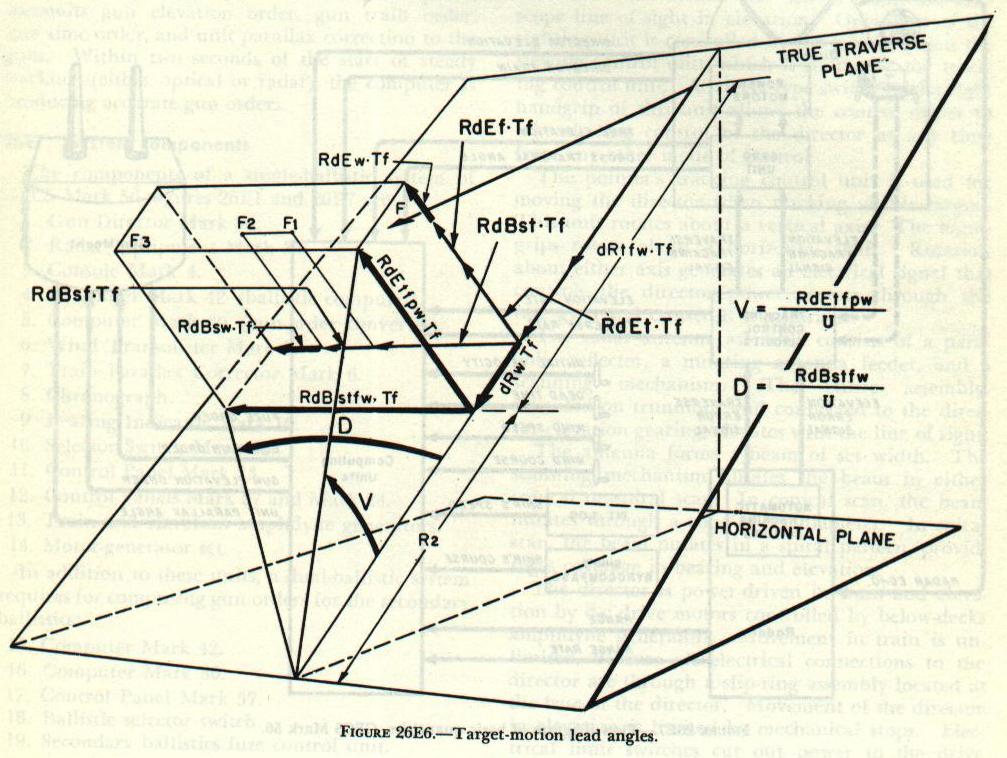
The lead angles V and D, shown in figure 26E6, are in the true elevation and true traverse planes.

Since present target position is measured in deck coordinates, the lead angles must be converted into their equivalent angles in deck coordinates. This conversion is performed in the Mark 30 computer by a graphic device called the axis converter. The converter is a small dummy-gun arrangement which reproduces the actual conditions of the problem. The stabilized lead angles are set into the converter, and the correct values of lead angles in deck coordinates are continuously picked off and used in making up gun orders.

Parallax correction is accomplished in three parts: (1) an elevation correction to account for the vertical displacement of the gun mount from the director, (2) a correction to director train to correct for the fore-and-aft displacement of the director from the ship’s reference point, (3) unit parallax correction (100-yard base length), which is transmitted to the gun mount, where a correction is made to gun order for displacement of gun mount from reference point.

26E5. Composition of gun orders

With the lead angles V and D in true coordinates converted to the deck-plane coordinates as V'd and D'd they can be added to E'b and B'r'. Gun elevation order E'g=E'b~V'd and gun train order, B'gr==B'r'+ D'd. These values are transmitted to the gun, where a final correction for horizontal gun parallax is introduced into gun train order.

The fuze setting order (F) for mechanical time fuzes is computed in the Mark 42 computer.

26E6. Summary of system operation

26E7 
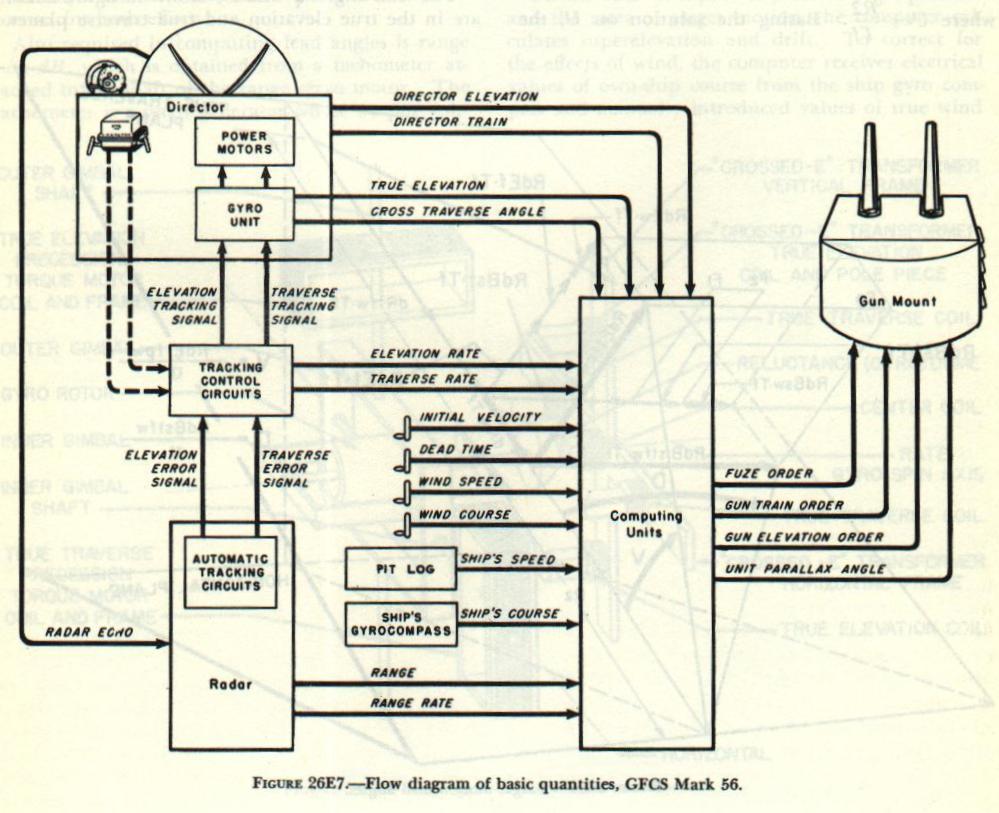
Figure 26E7 shows the flow of basic quantities in the system when using automatic radar tracking, which is the usual method of operation. The radar equipment in the radar room receives target echoes from the antenna and transmits traverse and elevation error signals to the gyro unit as tracking signals and to the computer as rates of target motion. By resetting the control switches, signals from the optical tracking control unit in the director may be selected in place of radar error signals. The radar equipment transmits range and range rate to the computer during both radar and optical tracking.

In the gyro unit, tracking signals are added to stabilizing signals. The resultant signals control the director power drives. As the director tracks the target, director position is measured by synchros, and director train and elevation are transmitted to the computer. The gyro unit also transmits values of true director elevation and cross-traverse angle to the computer.

Own-ship course and speed are introduced to the computer electrically from the gyro compass and pitometer log, while true wind speed and direction, initial velocity, and dead time are introduced manually. The computer calculates lead angles and ballistic corrections, and makes up and transmits gun elevation order, gun train order, fuze time order, and unit parallax correction to the guns. Within two seconds of the start of steady tracking (either optical or radar), the computer is producing accurate gun orders.

26E7. System components

The components of a single-ballistic system of GFCS Mark 56, figures 26E1 and 26E7 are:
1. Gun Director Mark 56.
2. Radar Equipment Mark 35.
3. Console MARK 4.
4. Computer Mark 42 (ballistic computer).
5. Computer Mark 30 (gun-order converter)
6. Wind Transmitter Mark 5.
7. Train Parallax Corrector Mark 6.
8. Chronograph.
9. Bearing Indicator Mark 10.
10. Selector Switch Mark 13.
11. Control Panel Mark 23.
12. Control Panels Mark 27 and Mark 28.
13. Train and elevation amplidyne generators.
14. Motor-generator set.
In addition to these units, a dual-ballistic system requires for computing gun orders for the secondary ballistics:
15. Computer Mark 42.
16. Computer Mark 30.
17. Control Panel Mark 57.
18. Ballistic selector switch.
19. Secondary ballistics fuze control unit.
26E8 
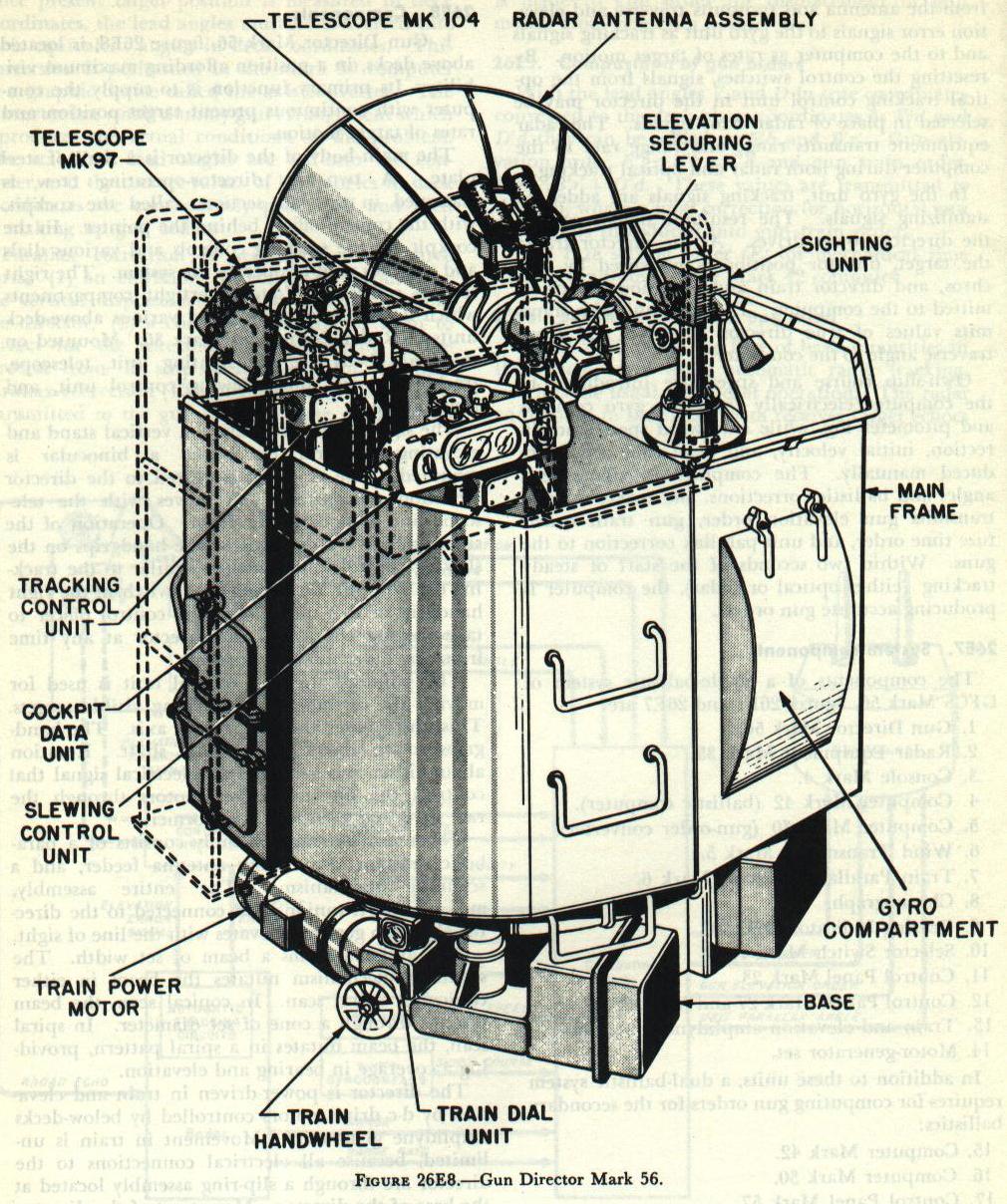
1. Gun Director Mark 56, figure 26E8, is located above decks, in a position affording maximum visibility. Its primary function is to supply the computer with continuous present target position and rates of target motion.

The main body of the director is a shell of steel plate. A two-man director-operating crew is stationed in the left section, called the cockpit, with the control officer behind the pointer. In the cockpit are the tracking controls and various dials and switches used to operate the system. The right section consists of four watertight compartments which house the gyro unit and various above-deck units of Radar Equipment Mark 35. Mounted on the main body are the sighting unit, telescope, tracking control unit, slewing control unit, and radar antenna.

The sighting unit consists of a vertical stand and elevating crossarm on which a binocular is mounted. The crossarm is geared to the director elevation transmitters and moves with the telescope line of sight in elevation. Operation of the sighting unit is controlled by the handgrips on the slewing control unit, which is similar to the tracking control unit. A trigger-type switch in the right handgrip of this unit allows the control officer to take slewing control of the director at any time from any other mode of control.

The pointer’s tracking control unit is used for moving the director when tracking visible targets. This unit rotates about a vertical axis. The hand-grips rotate about a horizontal shaft. Rotation about either axis generates an electrical signal that controls the director power motors through the rate gyro and crossed-E transformer.

The radar antenna assembly consists of a parabolic reflector, a nutating antenna feeder, and a scanning mechanism. The entire assembly, mounted on trunnions and connected to the director elevation gearing, elevates with the line of sight.

The antenna forms a beam of set width. The scanning mechanism nutates the beam in either conical or spiral scan. In conical scan, the beam nutates through a cone of set diameter. In spiral scan, the beam nutates in a spiral pattern, providing a coverage in bearing and elevation.

The director is power-driven in train and elevation by d-c drive motors controlled by below-decks amplidyne generators. Movement in train is unlimited, because all electrical connections to the director are through a slip-ring assembly located at the base of the director. Movement of the director in elevation is limited by mechanical stops. Electrical limit switches cut out power to the drive motors before the mechanical limit stops are reached.

The director is provided with locks for securing in train and elevation when the director is not in use. Securing locks incorporate a protective micro switch that cuts out power to the amplidyne generators when either lock is in the secured position.

A train handwheel and an elevation handknob are provided so that the director may be moved for securing purposes when the power motors are off.

For transmitting values of train and elevation, the director is provided with synchro transmitters connected to the train and elevation drive-gear systems.

2. Radar Equipment Mark 35 supplies: (a) the computing units with continuous values of target range and range rates for both optical and radar tracking; and (b) the director with signal for tracking obscured targets. Once on target, the system will track automatically when radar control is being used.

Components of Radar Equipment Mark 35 located above decks are the antenna, scanning mechanism and motor, transmitter, and receiver. The radar indicators, range controls, adjustment controls, and automatic tracking circuits are located below decks on Console Mark 4.

3. Console Mark 4, figure 26E1, is the below-decks operational center. On it are the knobs, dials, and indicators necessary for below-decks operation of the system. While various phases of the computations are performed in separate computing units, inputs and power to these units are controlled from the console.

The console consists of four main sections: a dial section at the top, the radar section, the operational section, and Computer Mark 42 at the bottom. Bearing Indicator Mark 10 is mounted on the right side of the console.

On the face of the dial sections are knobs and dials for hand inputs to computing units; dials indicating range, elevation, and bearing; cracking-control indicating lamps; and a switch controlling computer operation.

The radar section consists of five panels containing the A/R-indicator, E-indicator, and B-indicator and switches for controlling radar operation.

The operational section contains the handknobs, slew levers, and switches for controlling the director in train and elevation, and for controlling range, antenna scan, and modes of operation. E-9 
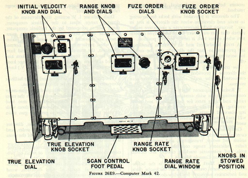
4. Computer Mark 42, figure 26E9, is the ballistics computer. Its primary function is to compute projectile time of flight, superelevation, drift, range rate, and fuze order.

Dials indicate I. V. setting, true elevation of the director, range input to the ballistic computer, range rate as computed by the ballistic computer, and fuze order being transmitted to the guns. Knobs are provided for setting these values manually when performing tests; however, for normal operation, the true-elevation, range-rate, and fuze-order knobs are removed from their sockets and stowed as shown in figure 26E9, and the range knob is disengaged. Only the initial velocity (I. V.) knob remains engaged.

The pedal below the center panel of the ballistic computer controls the type of antenna scan.

5. Computer Mark 30 is called the gun-order converter. Its basic function is to convert the rates of target motion in true coordinates into lead angles in deck coordinates, and combine them with director train and elevation to produce gun train and elevation orders.

Four dials indicate director elevation, director train corrected for parallax, gun train order, and gun elevation order. The input value of the cross-traverse angle is visible through a window.

6. Wind Transmitter Mark 5 computes corrections to compensate for the effect of wind on projectile flight, and transmits them to the gun-order converter for inclusion in the solution of the problem. Electrical inputs of wind direction, wind speed, and ship speed are received from the console. A dial on the face of the wind transmitter indicates the direction from which apparent wind is blowing.

7. Train Parallax Corrector Mark 6 computes a correction for the displacement of the gun mount from the director along the ship’s fore-and-aft axis. It receives values of range, elevation, and director train. The outputs are: (a) director train corrected to the ship reference point which is transmitted to the gun-order converter; (b) unit parallax correction, which is transmitted to the gun for correcting the value of gun train order. A dial indicates the unit parallax correction.

8. The chronograph measures the average velocity of the projectile, so that I. V. may be determined accurately.

9. Bearing indicator Mark 10 indicates director bearing (both relative and true) to the below-decks operating crew.

10. Selector Switch Mark 13, also called the Computer Mark 1A switch, is installed only on ships where GFCS Mark 56 is to be connected with Computer Mark 1A for surface fire. In the Computer Mark 1A position, the switch allows values of director train and range to be transmitted to Computer Mark IA.

26E9. Dual-ballistics units

A dual-ballistic system tracks one target but computes two sets of gun orders for guns of different ballistics. For example, in a typical light-cruiser installation, GFCS Mark 56 computes gun orders for 3”/50 and 6”/47 guns.

The dual-ballistics system requires a second Computer Mark 42 for the secondary ballistics, using the same inputs as the primary ballistics computer, and a Computer Mark 30 which computes gun train order and gun elevation order for the secondary ballistics.

The ballistic selector switch controls power to the secondary ballistics-computing units. It has two positions; PRIMARY and BOTH. The secondary units are energized when this switch is in BOTH.   Bottom of Page 2

A. Fire Control Problem
B. Basic elements of lead-computing sights
C. Gun sight Mark 15

D. Gun Fire Control System Mark 63

E. Gun Fire Control System Mark 56, Page 1
E. Gun Fire Control System Mark 56, Page 2 (This Page)
E. Gun Fire Control System Mark 56, Page 3
E. Gun Fire Control System Mark 56, Page 4
E. Gun Fire Control System Mark 56, Page 5