INDEX Back to Main Fire Control Page
A. Fire Control Problem
B. Basic elements of lead-computing sights
C. Gun sight Mark 15
D. Gun Fire Control System Mark 63
E. Gun Fire Control System Mark 56, Page 1
E. Gun Fire Control System Mark 56, Page 2
E. Gun Fire Control System Mark 56, Page 3
E. Gun Fire Control System Mark 56, Page 4
E. Gun Fire Control System Mark 56, Page 5 (This Page)
E. Gun Fire Control System Mark 56 Pg 5
26E14. Summary of operational controls-tracking control switching
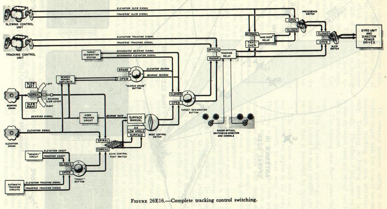 Figure 26E16
 shows the functional arrangement of all controlling units and switches affecting tracking control.
All signals for positioning the director are introduced into the gyro unit, where they are combined with the stabilizing signals and then transmitted to the director drives.
The slew switch takes precedence over all other switches. When closed, it allows only signals from the slewing sight to be introduced to the gyro unit, except when the precedence switch is also closed; then either the tracking control unit or the console can override the slew signals, if the appropriate take-over switch is closed. The position of the radar-optical switch determines which of these two stations can take control.
Next in importance after the slew switch is the radar-optical switch. When on OPTICAL, it selects only the signals from the tracking control unit; when on RADAR, it allows signals from the console to take over.
The target-designation push button takes precedence over all other console controls. When closed, it selects the designating signals from the target designating station. Signals from the bearing and elevation cranks on the console may be introduced to search within ±20 degrees of designated values.
When the mode control switch is set at SURFACE MANUAL, the bearing crank on the console has control of director bearing. Either manual or automatic tracking in elevation is possible, depending on the type of scan control in use. The other three positions of the mode control switch allow full automatic tracking, depending on scan control.
The scan control foot switch serves the function of choosing between manual and automatic tracking. With the scan control in SPIRAL, only manual tracking (with the bearing crank, slew lever, and elevation crank) is possible. The bearing crank signal goes through only if the bearing slew lever is set at NORMAL.
Automatic tracking is possible only in conical scan. The memory circuits are substituted for the automatic tracking circuits when the coast push button is pressed. The automatic tracking circuits will control the director if: (1) the coast push button is on OPEN; (2) the scan control pedal is on CONICAL; (3) the mode control switch is set at AA, SURFACE, or LOW ANGLE; (4) the target-designation push button is on OPEN; (5) the tracking switch is in RADAR and (6) the slew switch is OPEN, or, if closed, when the precedence switch is also closed so as to activate the TAKE-OVER mode of the take-over relay. The scan control foot switch serves as the take-over switch for radar tracking, actuating the TAKE-OVER mode in conical scan.
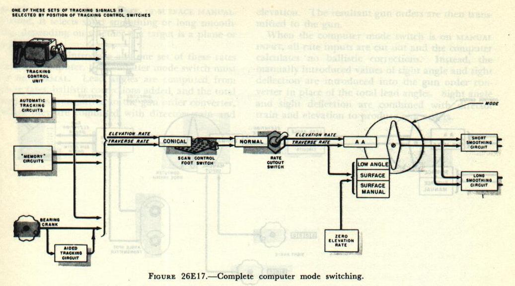
Computer mode switching.
Figure 26E17 shows the controls affecting computer operation. The elevation and traverse rates introduced into the computer for computing lead angles are the same as those transmitted to the gyro unit for positioning the director. However, the computer does not receive slewing rates nor, generally, rates from the console cranks.
The only traverse and elevation rates received by the computer are those from: (1) the tracking control unit, (2) automatic tracking circuits, (3) memory circuits, and (4) the bearing crank when the mode control switch is set at SURFACE MANUAL. The mode control switch serves a dual function. First, it substitutes zero elevation rate when in positions: Low ANGLE, SURFACE, or SURFACE MANUAL. Second, it selects short smoothing or long smoothing, depending on whether the target is a plane or a ship.
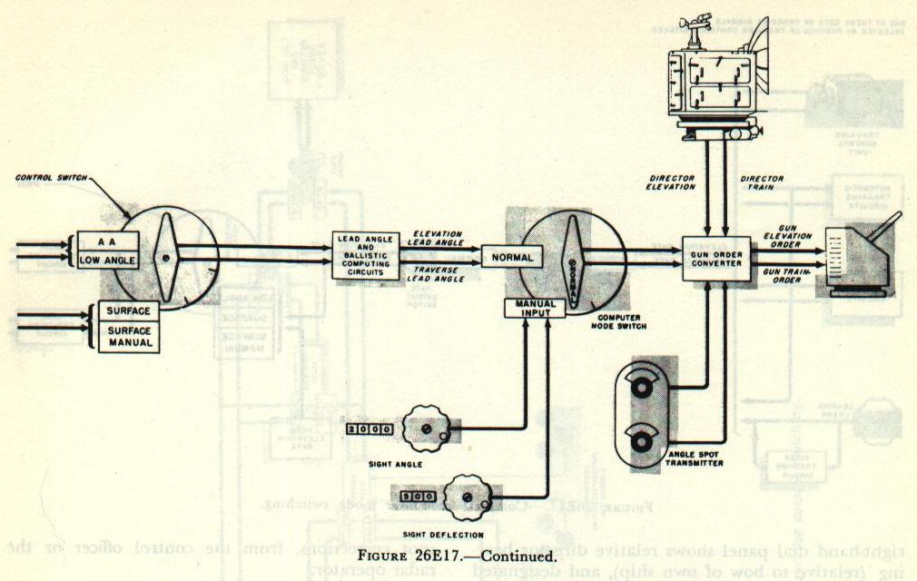
In order to introduce any one set of these rates into the computer, the computer mode switch must be on NORMAL. Lead angles are computed from these rates, ballistic corrections added, and the total lead angles transmitted to the gun order converter, where they are combined with director train and elevation. The resultant gun orders are then transmitted to the gun.
When the computer mode switch is on MANUAL INPUT, all rate inputs are cut out and the computer calculates no ballistic corrections. Instead, the manually introduced values of sight angle and sight deflection are introduced into the gun order converter in place of the total lead angles. Sight angle and sight deflection are combined with director train and elevation to produce gun orders.
Bottom of Page 5
