| GENE SLOVER'S US NAVY FIRE CONTROL PAGES NAVAL ORDNANCE AND GUNNERY VOLUME 2, FIRE CONTROL CHAPTER 27 TORPEDO FIRE CONTROL |
| HOME INDEX Chapter 27 Torpedo fire control A. General B. Destroyer torpedo fire control problem C. Destroyer torpedo fire control system D. CIC's function in the radar-aim torpedo attack |
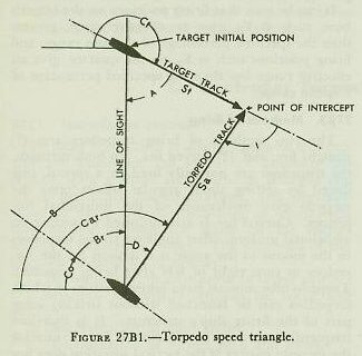
| B. Destroyer Torpedo Fire Control Problem 27B1. The torpedo speed triangle Before proceeding with a study of the fire control instruments and methods of controlling torpedo fire, certain basic elements in the problem must be understood. Figure 27B1 is the basic speed or vector triangle of torpedo fire. It is a graphic representation of the intercept problem in which the torpedo is directed along the correct course to hit the target. Definitions associated with this triangle are as follows: 1. Firing point. The point where the torpedo begins its run; broadly the position of the firing ship when the torpedo is launched. 2. Point of aim. The desired point on the target to be hit with the torpedo. 3. Point of intercept. The point where the torpedo hits the target or crosses the target’s track (or target’s track extended). 4. Line of sight. The straight line from the axis of rotation of the torpedo director to the point of aim on the target. 5. Target speed, St. Speed of the target in knots. 6. Torpedo speed, Sa. The average speed in knots of the actual torpedo from the tube muzzle to the point of intercept. 7. Target angle, A. The relative bearing of the firing ship from the target. Target angle is measured clockwise from the target’s bow to the line of sight between target and firing ship. (A = B + 180° - Ct.) 8. Track angle, I. The angle at the point of intercept between the target’s course and the reverse course of the torpedo, measured clockwise from the target’s course. The ideal track angle is usually considered to be 90° or 270°, because under such conditions the target ship is squarely broadside to the torpedo track, thus offering the largest target area. 9. Basic sight angle, D. The computed angle from the line of sight to the final track of the torpedo, measured clockwise. It must be emphasized that D is independent of range; it is, however, dependent on torpedo speed, which must be decreased if ranges are excessively long. The sight-angle solution is affected by the following factors: a. Line of sight-determined visually or by radar. b. Target angle or target course-estimated or found by tracking. c. Target speed-determined by eye estimate, or by tracking. d. Torpedo speed-known in advance from the speed setting ordered. |
 |
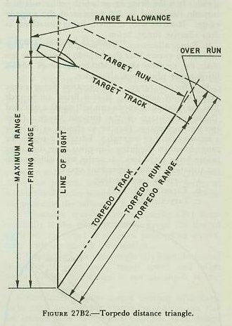 |
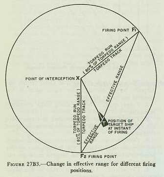
| 27B2. The torpedo distance triangle The speed and distance triangles of torpedo fire are similar and may be superimposed. However, it is important for the student to recognize that these two triangles are constructed with different scales, and therefore must be used independently in the two parts of the problem. The distance triangle is shown in figure 27B2. Definitions associated with the distance triangle are as follows: 1. Torpedo track. The line along which the torpedo travels through the water after it has steadied on its set course. 2. Target track. The line along which the target is moving. 3. Torpedo range. The distance in yards which a torpedo is designed to travel before its speed falls off. 4. Torpedo run. The distance in yards which the torpedo travels from the firing point to the point at which it crosses the target’s track (or target’s track extended). 5. Target run. The distance run by the target during the time of torpedo run. 6. Overrun. The distance in yards which a torpedo will run at its designed speed after crossing the target’s track, (or track extended). Torpedo range equals torpedo run plus overrun. 7: Firing range. The distance in yards between the firing ship and the target at the instant of firing. 8. Maximum range. The greatest firing range at which a torpedo may be fired and have sufficient endurance to intercept the target at its designed speed. It is the firing range which will result in a torpedo run equal to 100 percent of the torpedo range. It varies with different firing situations, as does effective range, below. 9. Range allowance. The margin of firing range allowed to ensure that the torpedo run will be less than the torpedo range. Maximum range equals firing range plus range allowance. 10. Effective range. The greatest firing range permitted by doctrine. It is a firing range such that the resultant torpedo run will equal a specified (high) percentage of the torpedo range. (The specified percentage may be so chosen as to leave a small amount of overrun.) Effective range is the range to which the firing ship must close the target before firing torpedoes. It varies with different firing situations, being dependent upon: a. Torpedo speed setting. b. Target speed. c. Target angle. Figure 27B3 illustrates the effective range circle of torpedo fire. The line TX represents the distance and direction the target will travel while the torpedo travels a specified percentage (as in 10 above) of its designed range. The circle represents the locus of all firing positions for an effective range shot for the particular target speed and torpedo speed on which the diagram is based. It can be seen that firing positions on the target’s bow, such as F1, give an effective range greater than the specified percentage of torpedo range, and firing positions such as F2, on the quarter, give an effective range less than the specified percentage of torpedo range. |
 |
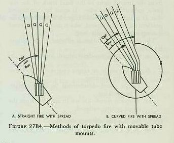 |
| 27B3. Methods of firing The two methods of firing torpedoes are: (1) straight fire, and (2) curved fire. In both methods, the torpedoes are normally fired in a spread, produced by setting small angular offsets onto the torpedo gyro mechanism of the individual torpedoes. Curved fire is accomplished by setting an additional uniform offset angle on all the torpedoes in the mount to the angle it is desired for the torpedoes to turn right or left after being launched. Torpedo-tube mounts have limited sectors in which torpedoes can be launched without striking some part of the firing ship’s structure. It is therefore frequently necessary to use curved fire to unmask the torpedo battery if the tactical situation does not permit changing course. The two methods of firing torpedoes are shown in figure 27B4, along with further elements of the torpedo control problem. Definitions associated with these figures are as follows: 1. Basic tube train, Bur. The computed angle between the fore-and-aft axis of the firing ship and the axis of the torpedo-tube mount, measured clockwise from the firing ship’s bow. 2. True torpedo course, Ca. The angle between the north-south line and the final mean track of the actual torpedoes, measured clockwise from north. 3. Relative torpedo course, Car. The angle between the fore-and-aft axis of the firing ship and the final mean track of the actual torpedoes, measured clockwise from the firing ship’s bow. 4. Gyro angle, G. The angle between the axis of the torpedo-tube mount and the final mean track of the torpedoes, measured clockwise from the axis of the tube mount. 5. Spread angle, Q. The angular difference between the final track of two adjacent torpedoes fired from the same tube mount, after algebraic addition of any angular change caused by relative target motion during the firing interval. |