| NAVAL ORDNANCE AND GUNNERY VOLUME 2, FIRE CONTROL CHAPTER 29 MISSILE CONTROL AND GUIDANCE SYSTEMS |
| HOME INDEX Chapter 29 Missile control and guidance systems A. Introduction B. Control systems C. Basic guidance systems |
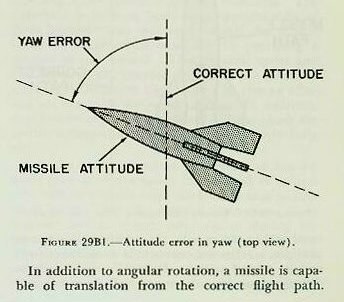
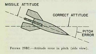
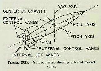
| B. Control Systems 29B1. Introduction A guidance system is a robot device capable of directing the flight of a missile in response to intelligence set into it, or to commands originating from outside the missile. The functions of such a system are to stabilize the missile axes with respect to a desired flight path and to orient the missile with respect to a target. Figure 29B5 shows the three mutually perpendicular axes (yaw, pitch, and roll) which the guidance system must be capable of positioning correctly to accomplish the above functions. A missile in flight is subject to angular rotation about the yaw, pitch, and roll axes. Figures 29Bl and 29B2 show a missile with a yaw error and a pitch error respectively. If the missile is to remain stabilized with respect to the flight path, devices within the missile must be capable of detecting, measuring, and correcting yaw and pitch errors in order to keep the nose of the missile always pointed along the flight path. In addition, for the missile control vanes to function properly, the missile must not be permitted to roll about its longitudinal axis. Control of the angular motion of the missile about the yaw, pitch, and roll axes is called attitude control. Each guidance system must contain an attitude control system. |
 |
 |
 |
 |
 |
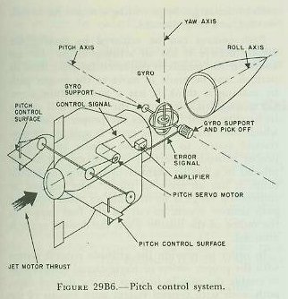 |
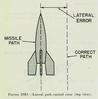
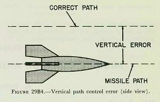
| In addition to angular rotation, a missile is capable of translation from the correct flight path. Figures 29B3 and 29B4 show a missile with a lateral error and a vertical error respectively. In addition, a missile may develop a range error along the desired flight path. Control of the translation of the missile with respect to its flight path is called path control. Each guidance system must contain a path control system, the function of which is lateral control, vertical control, and range control. 29B2. Attitude control system Control of the angular rotation of the missile about each of its three axes is accomplished by the attitude control system, all units of which are located within the missile. In addition, this system provides a reference common to both the missile and its control unit(s). It enables the missile to distinguish up from down and right from left, and to determine when it is rolling. For example, assume a missile is not roll-stabilized, and for some reason has rolled upside down. If a signal sent from the control unit ordered the missile to turn right, it would turn left, since it has no way of knowing that it is on its back. In general, the following components are used to achieve attitude control in a guided missile: a reference, a detector, a controller, and control devices to turn the missile about its yaw, pitch, and roll axes. Figure 29B6 shows how these components might be utilized in the pitch attitude control system of a missile. Similar components would be utilized in the same missile for the yaw and roll attitude control systems. 1. A reference is some device which will give the missile a known line in space from which to measure attitude errors. An example of a reference device is the gyroscope, whose attitude is fixed with respect to space. The orientation of the gyro spin axes with respect to the missile would depend upon the operational and design requirements of the missile. For example, in a surface-to-surface missile designed to maintain level flight with respect to the earth, the gyro spin axis would be set in the missile to coincide with the true vertical with respect to earth. Then any angular movement in yaw pitch will be in a plane parallel to the earth’s surface and in a plane perpendicular to the earth’s surface respectively. If the gyro is to be employed for very long periods of time or while the missile is moving over an appreciable part of the earth’s surface, a primary reference such as the magnetic compass or average position of a pendulum must be used to keep the gyro spin axis precessed to the true vertical. For an air-to-air missile designed to keep its nose pointed toward the target, it might be desirable to keep the gyro axis always perpendicular the missile flight path. In this application, an additional device, as a radar, would be required to determine the flight path and continuously keep the gyro spin axis precessed to the correct position. If the gyro is to be employed as the reference device, one gyro can serve as a reference for any two of the three types of attitude control (yaw, and roll). Normally, two gyroscopes are one for the yaw and pitch control systems, and one for the roll control system. 2. A detector is a device that will measure any error that develops throughout the flight of the missile. If, for example, the gyroscope is used as a reference, a simple potentiometer can be used for the detector. If the potentiometer resistor is attached to the missile casing and the potentiometer wiper or arm is attached to a gyro gimbal shaft, any movement of the missile (and hence the resistor) will vary the position of the wiper on the resistor and cause the detector to measure a voltage proportional to the deviation of the missile from its correct attitude. This voltage, which will be very small, is used as the error signal. 3. A controller is a power device that is controlled by the small error signal. Since the signal detected is usually very small, it must be amplified before it can be used to drive servo motors to which are connected elements that cause motion of the missile about the various axes (yaw, pitch, roll). The controller usually consists of an amplifier and the necessary servo motors connected with it. 4. Various types of control devices positioned by the controller servo motor cause angular movement of the missile about the yaw, pitch, and roll axes. a. External control vanes or movable fins mounted externally on the missile, and similar to the rudders or elevators on a conventional aircraft, can be moved in the stream of air passing over the body. They will cause a greater force of air pressure to be built up on one side of the vane or fin than on the other, causing the missile to shift angularly in any direction desired. For both yaw and pitch, control vanes within one plane can be moved simultaneously in the same direction. For example, in figure 29B5 we can achieve yaw control by moving vanes A and B in the same direction, and the missile will change course accordingly. To achieve pitch control, vanes C and D are moved simultaneously in the same direction. For roll control, it is necessary to develop a torque which will turn the missile about its longitudinal axis. To accomplish this, opposite control surfaces, such as A and B, are moved in opposite directions. The difference in pressure built upon opposite sides of these control vanes will tend to roll the missile about its longitudinal axis, thereby providing a method of roll control. These control vanes and fins, however, can operate only when the missile is traveling at velocities high enough to give an effective air flow past the vanes or fins. In addition, they will be of little use in missiles flying above the earth’s atmosphere where there is relatively little air. b. Jet vanes placed in the stream of hot exhaust gases from the motor can be used to control the missile’s attitude until the missile attains sufficient velocity for the external control vanes or movable fins to become effective, or during the time the missile is above the earth’s atmosphere. The operation is similar to that of the external vanes and fins. Control is achieved by the proper positioning of the jet vanes in the high-velocity exhaust gases, just as the control vanes are moved in the air stream, in order to produce missile motion in the desired direction. Jet vanes, however, have a limited life due to the extreme temperatures they must withstand. The normal life of the jet vanes in the German V-2 rocket was approximately 60 seconds. c. A gimballed motor is another device which may be used. The missile motor is mounted in a system of gimbals similar to the gimbal system used for a gyroscope. By causing the output of the controller servo motors to rotate the gimbals with respect to one another, the direction of the thrust of the motor can be changed, resulting in a change of heading of the missile. This device will operate at any missile velocity, and whether the missile is in or out of the atmosphere. |
| d. Auxiliary jets may also be used to change the direction of motion of a missile. They can be mounted around the periphery of the missile at its center of gravity to cause lateral or vertical displacement of the missile, or they can be mounted parallel to the main propulsion system so that the missile’s over-all line of thrust can be changed, thus creating a turning movement. When the reference, director, controller, and control devices are assembled and mounted in a missile, they provide the missile with the means for maintaining stable flight on the desired flight heading. Referring to figure 29B6, assume our missile on a given heading develops a pitch error. Movement of the missile in pitch causes rotation of the missile casing with respect to the gyro reference, thereby causing displacement of the detector resistor with respect to the detector arm or wiper. This movement, noted by the potentiometer detector, is measured as an error signal or voltage (proportional to the movement in pitch) and sent to the controller. Within the controller, the error signal is amplified and applied to the pitch servo motor. The pitch servo motor then moves the pitch control vanes to cause the missile to correct the pitch error. When the missile is once again at the correct attitude in pitch, the error signal has decreased to zero, and the control vanes have returned to their neutral position. 29B3. Path control system The path control system normally acts through the attitude control system. It must provide the orders or navigational information to the attitude control system to cause the missile to take the flight path for which the missile was designed. As explained above, the path control system must operate to keep the missile on its designed flight path to the target by providing a means for lateral, vertical, and range control. Path control can be achieved by making the missile believe it has an attitude error. For example, if the missile is displaced laterally from its path, it may be made to move to the proper path by making it think it has a yaw attitude error. Correcting this false error, the missile will change its heading until it reaches the proper position, at which time another false error is sent to the yaw control system to bring the missile back to its proper attitude. Vertical control can be accomplished in a similar manner by making the missile think it has an error in pitch. One method of controlling range is by utilizing an order from the path control system to cut off the fuel supply to the motor of the missile when the desired range is attained. In order to provide the attitude control system with the proper orders or navigational information to enable the missile to keep on the desired flight path, each path control system must consist of the following components: tracker, computers, directing devices. 1. Tracker. Before any intelligent commands can be sent to the missile, it is necessary to know the location of the missile with respect to the target. If the missile is not on the desired path to the target, the tracker will observe an error. The tracker may be in the missile, on the ground, or in the air. Tracking is accomplished optically, by radar, or by some means which utilizes a distinguishing feature of the target or missile against its background. For long range all-weather tracking, radar has been found most satisfactory. 2. Computers. The computers calculate directing signals for the missile by use of information from the tracker. The directing signals will tell the missile how much to move the control surfaces to properly position itself on the desired flight path. Computing may be accomplished on the ground, in the missile, or in both places. A missile may use more than one computing element. For example, an altimeter may be used to maintain the missile at the correct altitude, and an air log computer may be used to initiate a signal to cut off the fuel to the propulsion system when a pre-set range has been recorded. 3. Directing devices. Directing is the process of sending the computed order to the missile. This can be accomplished by sending radio or radar signals to a receiver in the missile when directing is to be accomplished from the ground. When directing is to be accomplished within the missile, the computed order is sent from one sub-component to another by electric, pneumatic, or hydraulic signals. The directing signal can now be introduced into the controllers of the attitude control system either to correct the missile’s lateral or vertical deviation from the desired flight path or to cause the missile to change course or altitude. In addition, the directing signal can be used to vary the propulsive force of the missile and hence the range. |