| GENE SLOVER'S US NAVY PAGES NAVAL ORDNANCE AND GUNNERY VOLUME 1, NAVAL ORDNANCE CHAPTER 7 TURRET INSTALLATIONS |
| HOME INDEX Chapter 7 Turret Installations A. Introduction B. Gun and breech assembly C. Slide assembly D. Elevating, traning and sight gear E. Ammunition handling F. Turrets equiped with case guns G. 6"/47 dual-purpose gun and turret H. 8"/55 rapid-fire gun and turret |
| D. Elevating, Training, and Sight Gear 7D1. Elevating gear The three elevating-gear installations of each turret are independent assemblies. Each assembly consists of an electric-hydraulic power drive, an oscillating bearing assembly, and control mechanisms, shown schematically in figure 7D1. The greater part of these assemblies are located below the respective guns, forward and below the gun pockets in the pan and machinery floor spaces. The arrangements on these levels are shown in figures 7A3 and 7A4. |
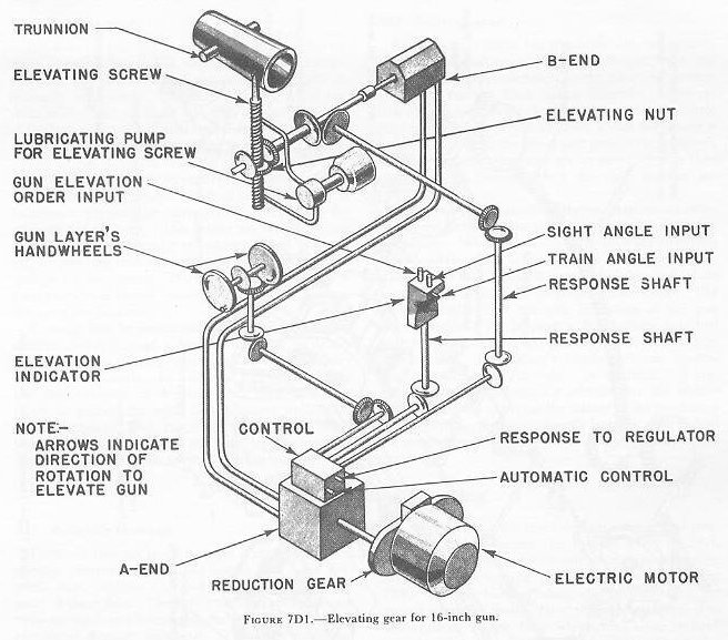 |
| The electric-hydraulic power drive has a 60-horse-power electric motor driving a variable-displacement hydraulic pump (A-end) which supplies oil pressure to a fixed-displacement hydraulic motor (B-end), as described more completely in chapter 10. The B-end output shaft is connected to the elevating-nut drive. (See fig. 7D1.) The elevating nut is threaded around the elevating screw and is mounted in the oscillating bearing (not shown in fig. 7D1), which allows the complete assembly to tilt. The elevating screw is secured to the pivot pin on the rear end bracket of the gun slide, and is moved up or down as the elevating nut rotates. Gun-elevating movement is controlled automatically by means of a receiver-regulator or by rotation of the gun layer’s handwheels on the machinery floor. In the latter method the gun-laying personnel (one gun layer for each gun) control the power drive in accordance with dial-indicated gun-elevation orders emanating from either the director system or one of the two sighting stations within the turret. Elevation stops are installed to limit elevation and depression to 45 degrees and minus 2 degrees respectively. The maximum elevating speed is approximately 12 degrees of arc per second. After firing the gun is automatically lowered to the loading angle of five degrees elevation by operation of a control lever. |
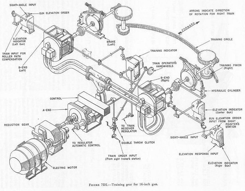 |
| 7D2. Training gear The training gear and its control equipment shown schematically in figure 7D2, also consists of an electric- hydraulic power drive which can be automatically or manually controlled. The electric motor (300 hp, with an overload rating of 540 hp) drives the A-end of the hydraulic transmission unit through a reduction ear. Two B-end units are driven by the single A-end. The B-ends drive, the training pinions, which mesh with the training circle secured to the turret foundation. The brakes between the B-ends and the pinions function to prevent the turret from turning when the training power is off. The brakes are set by springs and released by hydraulic cylinders. When power is off, no pressure is in the hydraulic cylinders, and the springs set the brakes. During training, a piston in each cylinder is forced upward by oil under pressure, releasing the brakes. Training may be automatically controlled from the director system through a receiver-regulator, or locally controlled from cither the gun deck or the machinery floor by handwheels. In indicator gun laying, either the train operator on the machinery floor trains the turret in accordance with dial-indicated train-order signals, received from the director system or turret sighting stations, or one of the sight trainers controls the drive by keeping his telescope on the target. 7D3. Sighting gear Each 16-inch turret has duplicate sight stations in enclosed compartments located outboard from the wing guns and approximately on the transverse center-line of the turret. Each station transmits gun elevation or gun train orders to the indicators and control gear on the machinery floor from which the power is actually applied to the turret and guns. The pointer's and the trainer’s telescopes are so mounted that they have parallel motions when the sight settings are made. Corresponding elements of the two stations are interconnected so that either station can take over sighting operations. When this is done, the guns are indirectly positioned from a sight station by first setting the sight. The pointer and trainer then turn their handwheels to keep the crosslines of the telescopes on the target. The pointer’s handwheel operates indicators at the gun layer’s station. By keeping a dial pointer matched with these indications, the gun layer positions the gun in elevation. The trainer’s handwheel can accomplish the same result in train. In addition it is possible, by use of appropriate selector, for the trainer in the gun house to bypass the trainer at the machinery level and move the turret directly in train, as he rotates his handwheel in keeping his vertical crosslines on the target. |