| GENE SLOVER'S US NAVY PAGES NAVAL ORDNANCE AND GUNNERY VOLUME 1, NAVAL ORDNANCE CHAPTER 7 TURRET INSTALLATIONS |
| HOME INDEX Chapter 7 Turret Installations A. Introduction B. Gun and breech assembly C. Slide assembly D. Elevating, traning and sight gear E. Ammunition handling F. Turrets equiped with case guns G. 6"/47 dual-purpose gun and turret H. 8"/55 rapid-fire gun and turret |
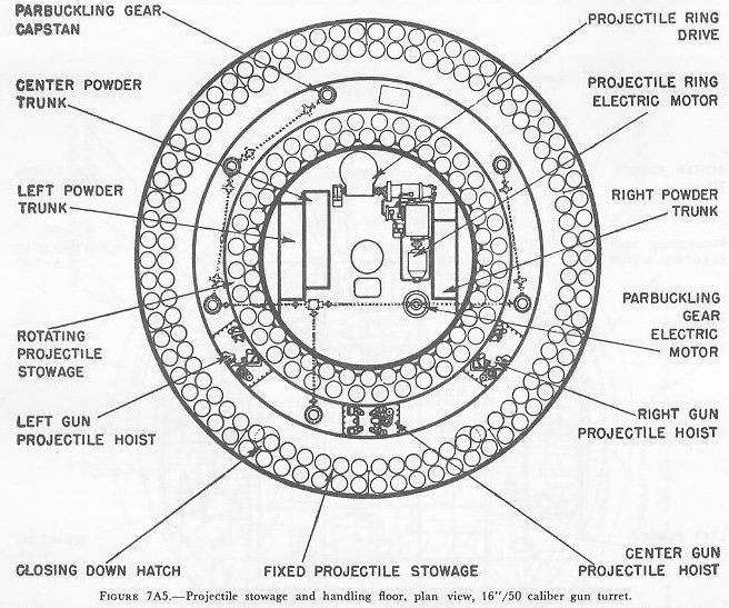
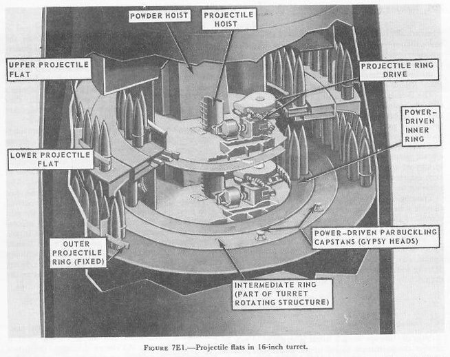
| E. Ammunition Handling 7E1. Projectile stowage Projectile stowage in each turret is arranged in two circular compartments, called upper and lower projectile flats. Figures 7A5 and 7E1 show the arrangement of these flats. The projectile stowage spaces are between the turret foundation bulkhead and an inner concentric circular bulkhead. The latter bulkhead surrounds machinery compartments at the center of each flat and separates them from the stowage and handling compartment. In each stowage compartment the floor is subdivided into three concentric ring-shaped platforms. The outer ring is a fixed shelf attached to the turret foundation and provides the “fixed” projectile stowage. The intermediate ring is part of the rotating structure and is the shell-handling platform. The three projectile hoists have loading aperatures in this intermediate ring. The inner ring is a roller-mounted platform supported by the turret rotating structure and has a power drive which can rotate the ring in either direction with respect to the intermediate ring. This inner ring provides the “rotating” projectile stowage. |
 |
 |
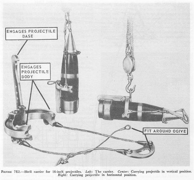
| Projectiles are brought to these stowages as follows: First, they land on the main deck in a horizontal position and a shell carrier (on the left in fig. 7E2) is fitted around them. An electric drum-type hoist then lowers them in vertical position (center item in fig. 7E2) through hatches alongside the turret to the second platform level. Here they are transferred to an overhead trolley, from which they hang in horizontal position (on the right in fig. 7E2). The trolley takes them under a hatch in the projectile flat, where they are transferred to an electric whip hoist which hauls them (in vertical position) up to the projectile flat to be stowed. The projectiles are lowered and hoisted one at a time; when each projectile reaches the flat, its carrier is removed and sent up to the main deck to be used again. The projectile’s are stowed standing on their bases, and each is separately lashed to the bulkhead. |
 |
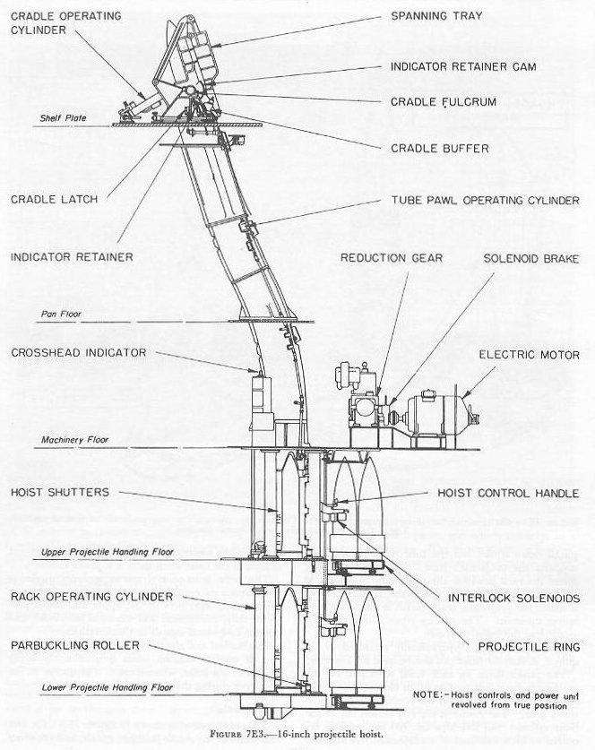
| With the projectile rings loaded and ready for use, the inner rotating projectile ring moves projectiles to positions near the hoists. All 3 hoists can be served simultaneously from 1 ring. Loading into the hoists is performed by parbuckling---passing a line around the projectile, leading the line to a power-operated capstan, and sliding the projectile along on its base. See figures 7A5 and 7E1. The parbuckling gear can also deliver the projectiles from fixed stowages to the rotating ring. Manual controls with automatic stop arrangements operate the rotating ring through arcs of 30 degrees to facilitate continuous delivery to the hoists. Three projectiles per minute per hoist can be delivered. 7E2. Projectile hoist Each gun has a projectile hoist which raises the projectiles from the stowage compartments in the turret rotating structure to the breech end of the gun. The hoist (see fig. 7E3) consists of a tube through which the projectile passes base downward, a hydraulic-ram-type lift, and power drive with its associated control. The three tubes pass through the middle rings of the projectile flats and are almost vertical up to the pan floor. From this point the two outboard tubes slope rearward at an angle to the cradles at the upper ends of the tubes. The center tube continues its vertical course, so that at the guns all cradles are equidistant from the breech. The hydraulic lift consists of a hydraulic cylinder vertically mounted between the decks of the projectile flats, a piston, and a piston rod which connects to a rack in the tube casing. The piston diameter is about 6 inches, and the piston stroke is approximately 8 feet. The hydraulic lift raises or lowers the projectiles one stage per stroke. The distance to the cradle is 4 stages from the lower projectile flat and 3 from the upper. The hoist contains 2 sets of spring-loaded pawls, 1 set on the rack connected to the hydraulic piston, and the other on the inner wall of the hoist tube. The pawls in each set are spaced one stage apart. The principles of operation of pawl-type hoists were explained in chapter 5. As the piston and rack move up, the lowest rack pawl picks up the projectile base and pushes it upward past the tube pawl at the next stage. Then the rack moves downward with the piston down stroke, but the tube pawl engages and supports the projectile’s base. The projectile body forces the rack pawl for the next stage to retract as the rack descends. At the end of the stroke, this pawl is under the projectile, ready to lift it when the rack moves up again. The process repeats until the projectile is at the top of the hoist. The pawls can be hydraulically retracted as required, so that the hoist can also be used for lowering. The power drive for each hoist is located on the machinery floor and consists of an electric motor (75 hp), a reduction gear, and the A-end of a hydraulic speed gear. The A-end is directly connected to the hoist cylinder and develops the 700 psi pressure required to lift a full load of 4 projectiles. A solenoid brake on the electric-motor shaft operates to prevent motion of the hoist when there is a power failure. The main hoist-control system includes duplicate installations of control handles at stations near the hoist-loading apertures in the upper and lower projectile flats, mechanical and electrical interlocks, and audible and visual signals at these stations. Mechanical and electrical interlocks prevent operation of control handles when projectiles are being loaded in the hoist, when there is a projectile in the cradle, or during the ramming cycle. |
 |
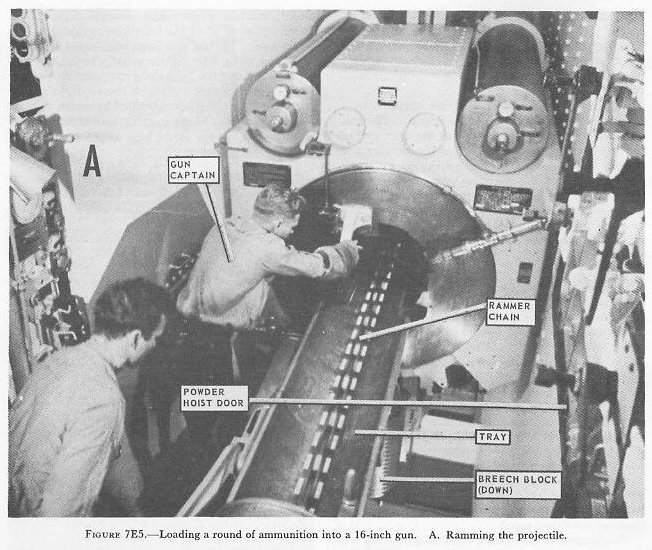
| 7E3. Cradle The cradle assembly shown in figures 7E3, 7E5, and 7E6 includes the cradle fulcrum, cradle, and spanning tray. During hoisting the rammer chain is in its retracted position, the cradle is upright so that its axis lines up with that of the hoist tube, and the spanning tray is folded against the cradle. A projectile hoisted into the cradle is supported there by a projectile latch within. The cradle and spanning tray are operated by a hydraulic cylinder not shown in the figures. The control lever for this unit is located at the after end of the gun compartment at the side of the rammer and cradle. When the control lever is operated, the cradle tips forward and the spanning tray moves forward and down, forming a smooth path from the hoist to the chamber. (Fig. 7E5.) The gun must be elevated to 5 degrees for loading, so that the tray lines up with the gun bore. 7E4. Rammer The rammer consists essentially of a special roller-type chain which meshes with a power-driven sprocket. The arrangement of parts is shown in figure 7E6. The rammer assembly is located in the turret officer’s booth just abaft the gun compartment. The power drive includes an electric motor (60 hp with an overload rating of 108 hp) a conventional hydraulic speed gear whose B-end drives the sprocket wheel. The control arrangement provides full-power projectile ramming to a jammed stop. This is necessary, since the rotating band must be forced into the rifling so that the projectile will not move to the rear when the gun is elevated. The maximum velocity during the ramming cycle is slightly less than 14 feet a second, and the time required for ramming is 1 .7 seconds. The powder bags are rammed into the chamber at a slower speed. |
 |
 |
 |
 |
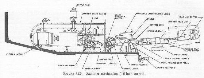 |
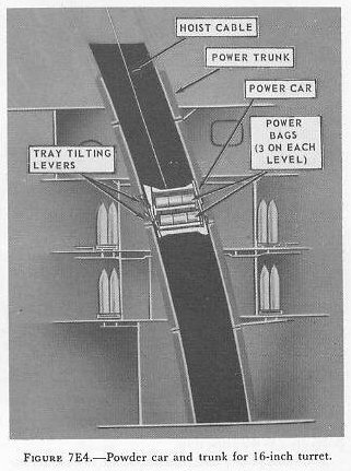
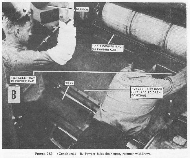
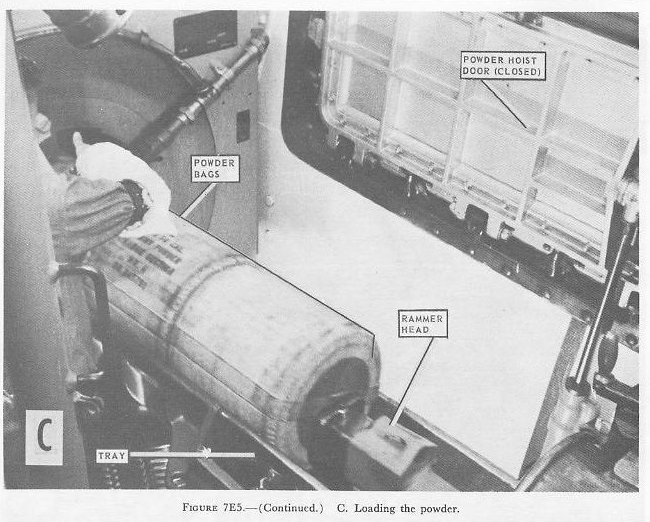
| The rammer chain forms a rigid column when it is extended. The chain assembly, including the head link buffer, is about 25 feet long. When in the “ready to ram” position the ramming head is about 8 inches behind the projectile base and 9 feet from the breech face. The projectile travel to full seat during ramming is about 19 feet. 7E5. Powder hoist The powder magazines are outside the turret foundation on the platform deck beneath the lower projectile fiat. The powder is passed manually through self-closing scuttles in the powder-handling room bulkheads and in the lower foundation, into the hoist-loading space around the lower end of the turret revolving structure, and delivered by hoists to the guns. An electric-hydraulic powered hoist is provided for each gun. Each hoist contains a powder car (fig. 7E4) which rides up and down like an elevator in a closed, inclined trunk which extends through the turret structure from the hoist-loading space to the turret roof. The car is a large box-shaped structure closed on three sides. Four guide wheels, mounted on the rear corners, ride along the after side of the trunk. The bags are carried on two vertically spaced trays which can be separately tilted by means of hand levers on one side of the car, A loaded car delivers a full-service charge of six bags to the gun without intermediate handling. The car is loaded in the hoist-loading space beneath the projectile flats, through an aperture in the trunk. This opening is sealed by a manually operated, vertically sliding door which must be closed before the car can be hoisted or lowered. It cannot be opened unless the car is in its loading position. Powder is delivered to the gun through a door located just abaft and to one side of the breech mechanism. The door swings outward and down, providing a shelf across which the powder bags roll from the car to the loading tray. (Fig. 7E5.) The door is operated by a hydraulic power device. When the delivery door is open, the car can be lowered, but not raised. The interlocking features make it impossible to have both the loading and the delivery doors open at the same time. The hoist power unit consists of an electric motor (100 hp) and a conventional hydraulic speed gear that drives a hoisting drum. This unit is located in the gun compartment next to the trunk. The ca r is lowered by gravity and hoisted by means of a 5/8-inch diameter wire rope which passes over a sheave under the turret top plate and thence to the hoisting drum. The hoist control is located at the hoist operator's station near the top of and abaft the trunk. Control arrangements include visual powder hoist indicators, starting and control selector levers, devices which limit acceleration and deceleration rates, door interlock switches, safety car-stop operating devices, and a power-failure brake on the hoist drum. The latter prevents the car from falling in case of power failure or rupture of hydraulic leads. 7E6. Loading operation A 16-inch 3-gun turret can be operated with a minimum crew of 77 men inside the turret. Station assignments for the turret crew are ordinarily as listed in the accompanying table. Station assignments, Turret crew .......Station.........................................................................Location Turret officer................................................Rangefinder and Turret Officers compartment. Turret officer's talker.....................................Rangefinder and Turret Officers compartment. Turret captain...............................................Rangefinder and Turret Officers compartment. Computer operators (2)..................................Rangefinder and Turret Officers compartment. Rangefinder operator.....................................Rangefinder and Turret Officers compartment. Rangefinder pointer.......................................Rangefinder and Turret Officers compartment. Rangefinder trainer........................................Rangefinder and Turret Officers compartment. Talker..........................................................Rangefinder and Turret Officers compartment. Sight trainer, right.........................................Right sight station Sight pointer. right........................................Right sight station Sight setter. right..........................................Right sight station Sight trainer, left...........................................Left sight station Sight pointer, left..........................................Left sight station Sight setter, left............................................Left sight station Plugmen (gun captains) (3)...........................Gun rooms Cradle operators (3).....................................Gun rooms Rammer operators (3)..................................Gun rooms Primermen (3).............................................Gun rooms Powder-hoist operators (3)...........................Top powder trunks. Gun layers (3)..............................................Machinery floor Gun train operator........................................Machinery floor Projectile hoist operators (3)..........................Projectile-handling floor (each level) Projectile-ring operator..................................Projectile-handling floor (each level) Shellmen (9).................................................Projectile-handling floor (each level) Electrician....................................................Projectile-handling floor (each level) Shell-deck P. O............................................Projectile-handling floor (each level) Powder-door operators (3)............................Powder-handling floor. Powder passers (9).......................................Powder-handling floor. Handling-room P. O......................................Powder-handling floor. In addition there are 6 powder passers in the annular space between the powder-handling room and the magazines, and 12 powder passers in the magazines. With the turret in all respects ready to fire and the power machinery in operation, the first command is: “Fill the powder train; fill the projectile hoists." At this command the necessary powder tanks in the magazines are opened; powder is passed through the scuttles to the lower handling room; the powder cars are filled and raised to the top of the hoists. BuOrd safety precautions require that in each flametight stage of the ammunition train, not more than one charge per gun, for the guns being supplied through that stage, shall be exposed or allowed to accumulate. Simultaneously the projectile-handling room crews are loading the projectile hoists with the required type of projectiles. This command further implies that whenever an empty powder car is returned to the lower handling room, or that whenever an empty stage in the projectile hoist appears, the crew must reload immediately until otherwise ordered. The first command to the gunroom is “Load.” The gun captain, on the loading platform, unlatches the breech operating lever and pushes it down. The primerman, under the breech, assists the gun captain in locking the breech down. The gun captain wipes the mushroom and inspects to see that the bore is clear. As soon as the “Bore clear” signal is given, the gun captain shuts off the gas ejector valve and signals the cradle operator to span the tray (lower it to loading position). At the same time the primerman inserts a primer into the open firing lock. The rammer operator rams the projectile (Fig. 7E5) until it is seated and with-draws the rammer as he opens the powder hoist door. The powder-car operator tilts 1 of the powder-car trays, and 3 bags of powder roll across the door onto the spanning tray. The gun captain and cradle operator guide the powder bags across the door and space them out on the spanning tray. The powder car lowers about 23 inches and stops automatically, and the remaining three bags powder art: rolled onto the spanning tray. (Fig. 7E5.) The rammerman closes the powder-car door and rams the six powder bags to place the rearmost bag not more than 4 inches from the mushroom when the breech is closed. The cradle operator folds he spanning tray as soon as the rammer is withdrawn. The gun captain releases the breech hold-down latch and opens the air valve to the closing cylinder. He then latches the operating lever as the plug rotates to the closed position. The gun captain steps off the loading platform and operates the "ready" switch to signal that the gun is loaded and to bring the gun to gun order position. |