| GENE SLOVER'S US NAVY PAGES NAVAL ORDNANCE AND GUNNERY VOLUME 1, NAVAL ORDNANCE CHAPTER 7 TURRET INSTALLATIONS |
| HOME INDEX Chapter 7 Turret Installations A. Introduction B. Gun and breech assembly C. Slide assembly D. Elevating, traning and sight gear E. Ammunition handling F. Turrets equiped with case guns G. 6"/47 dual-purpose gun and turret H. 8"/55 rapid-fire gun and turret |
| G. 6”/47 Dual-Purpose Gun and Turret 7G1. General The main battery of light cruisers of the CL-144 (Worcester) class comprises the newest design now in service of 6-inch guns and turrets. There are 12 guns in six 2-gun turrets, all of them capable of rapid fire against either air or surface targets. |
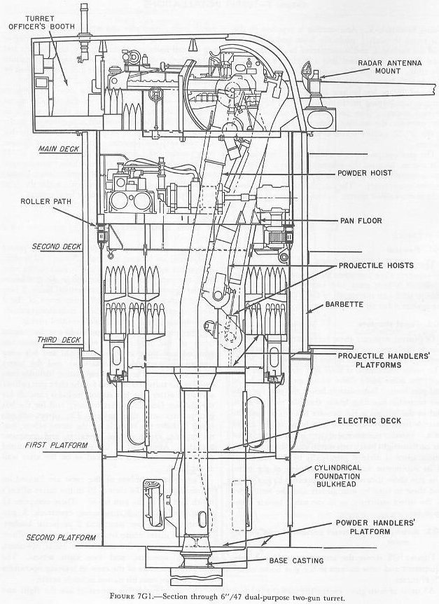 |
| 7G2. Turret structure In general structure these turrets are similar to the 6-inch triple-gun turrets discussed in the preceding section, though there are minor variations (fig. 7G1). The turret foundation is built into the ship and supports the roller path, above which are the gun house and pan floor. Immediately below the pan floor are two projectile-handling levels, then the electric deck, and at the bottom is the powder flat. The barbette extends from just below the gun house to the armor deck. Interior compartmentation is not severe; there are no flametight bulkheads subdividing the gun house, whose space is divided principally by the placement of its equipment and the arrangement of the guns. The gun slides themselves are supported by deck lugs, and these in turn by gun girders and the remainder of the turret structure, as in the other turrets taken up so far. |
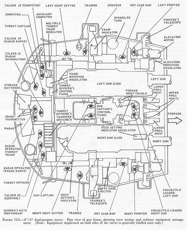 |
| 7G3. Arrangement of turret personnel and equipment Figure 7G2 shows the arrangement of ordnance equipment and crew stations in the gun house of the 6”/47 turret. All units of both guns, except the forward portions of the barrels and the power plants for the slide power equipment, are located in the gun house. (The slide equipment motor-pump units are located on the next level, the pan plate.) Also located in the gun house are the upper ends of the 6 ammunition hoists, 2 fuze setting indicator-regulators, all components of the 2 elevating-gear drives and their indicator-regulator controls, and the 2 gun captain’s control panels. Other major units in the gun house are the components of the fire control equipment. These are grouped into three stations: the right and left wing stations (also called sight stations) and the turret officer’s booth. The right wing station includes controls for the turret trainer and for the right gun pointer and sight setter; the left station includes controls for the checker (standby turret trainer) and for the left gun pointer and sight setter. The turret officer’s booth includes the controls for the turret officer, turret captain, radar control operators, and computer operator. Almost all of the equipment is mounted either on the forward bulkhead or on the after wall of the booth. Twenty-one members of the crew are located on the shelf plate of the turret; 10 in the turret officer’s booth and 11 in the gun house. These comprise 11 turret controlmen, 3 gun-laying operators, 3 gun operators, 2 hot-case men, and 2 projectile loaders. The 11 turret controlmen are: the turret officer, the turret captain, the talkers, the radar operators, computer operator, and two sight setters. The checker, a member of the crew in training operations only, does not man his station in battle action. The three gun-laying operators are the right and left pointers, and the trainer. The 3 gun operators are the 2 gun captains, 1 for each gun, and the gunner’s mate repairman, stationed in the turret officer’s booth for general maintenance of the gun control equipment. His principal responsibility is trouble correction; he also aids in preparing the guns for firing, in maintaining continuous operation of the guns, and in stowing the guns. The 2 projectile loaders are located 1 at the loading tray of each gun. They operate the fuze setting indicator-regulator when the fuze setting system is in manual control. The 2 hot-case men are located 1 on the outboard side of each gun near the case ejector. The pan plate (not illustrated) contains most of the components of training gear drive and the hydraulic power supply for the slide power equipment, as well as some of the equipment for the hoist power drives. |
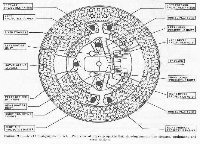 |
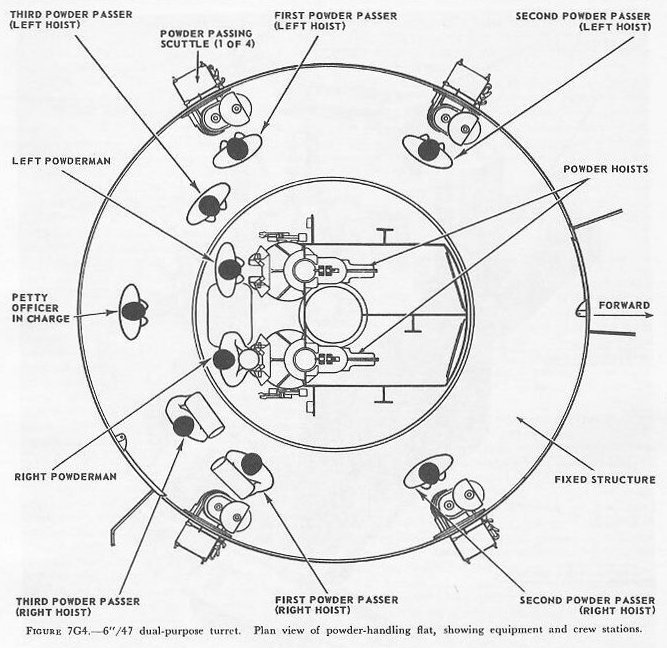
| The projectile-handling floor is divided into upper and lower projectile stowage flats. Much of the space at this level is taken up by hydraulic gear for the hoists and the train drive suspended from the overhead. Most of the rest is taken up by stowed projectiles and projectile hoists. Figure 7G3 shows the upper flat. The lower flat is generally similar, except that its diagram would show only 4 hoists (2 powder and 2 projectile) instead of the 6 visible in figure 7G3. Only two of the hoists shown open into the upper flat; the powder hoists and the projectile hoists from the lower flat are enclosed tubes passing through. This turret has but 1 projectile ring assembly, but the ring has 2 tiers, 1 for each flat. Each tier is set up to stow 288 projectiles. The projectile ring power drive has 4 control stations, 1 near each projectile hoist. The controls are operated in pairs; at each level, the hoist loaders on both sides must cooperate to start the ring. Fixed stowage capacity is 106 projectiles at the upper level, and 124 at the lower. Some sections of the upper flat are hinged so that they can be swung out of the way when the lower flat is in use. The same crew of 7 operates on either the upper or the lower flat. It consists of a petty officer in charge and 1 projectile loader and 2 passers for each hoist being served. The loaders merely shove projectiles into the hoists, which start automatically when loaded. The passers keep the loaders supplied; they also operate the projectile ring as required. At the powder-handling room level, four powder-passing scuttles admit powder cases from the magazine. A crew of 9 operates in the powder-handling room 6 powder passers taking the charges from the scuttles to the powder hoists, 2 powdermen operating the scuttles at the foot of the hoists, and a petty officer in charge (fig. 7G4). |
 |
| 7G4. Gun assembly The right- and left-hand gun assemblies are functionally identical, though some parts are of opposite hand. The two gun assemblies are symmetrically arranged about the turret centerline. The 6”/47 gun used in these turrets is a monôbloc radially expanded type, designed for semifixed ammunition, whose bore has 48 rifling grooves with right-hand uniform twist, 1 turn in 25 calibers. The gun housing has a vertically sliding breech-block operated by a hydraulic cylinder, and a single spade extractor, also hydraulically operated (fig. 7G5). |
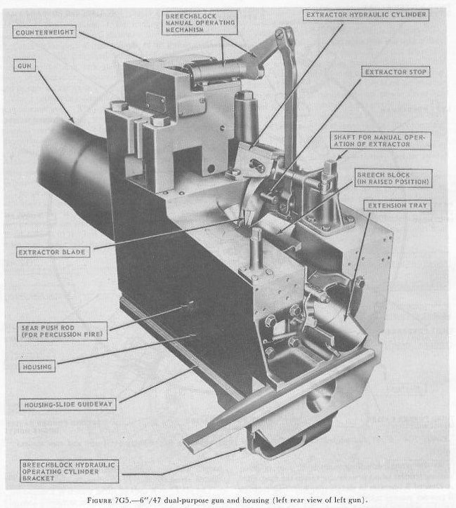 |
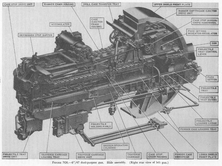
| The firing mechanism is designed primarily for electric primers, but it provides for percussion firing of short cases. The breech and firing mechanism and their power-operated components normally function automatically when the gun is firing, but they can be operated manually or by power under manual control. In general, the gun assemblies resemble those of 6”/47 guns in Cleveland class turrets. 7G5. Slide, rammer, and case elector In many ways, these assemblies are similar to those of the Cleveland class turret. This article will concentrate on the novel features. These are the mechanisms for loading the gun, fuze setting, and disposal of the empty case. Figure 7G6 shows the slide of the left gun. Mounted atop the slide is an accumulator from which is distributed the hydraulic fluid that operates the case extractor and breechblock in the gun housing and the projectile tray, case stop, traverse carriage, and ammunition rammer-empty case ejector in the slide. Most of these slide ammunition-handling units are at least partly visible in this view; the main exception is the empty-case tray at the left side of the slide. The pump that through the accumulator supplies the hydraulic fluid under pressure that drives all these units is on the pan floor, and the fluid flows to and from the slide through the three jointed pipes under the slide. The projectile is manually loaded into the projectile tray, and the powder case is mechanically loaded into the powder-case loading tray. The projectile tray drive unit then drives the projectile tray and fuze setter head aft. The powder-case crosshead, which is mechanically linked to the case-stop drive, engages the base of the case in the powder-case loading tray. The case stop drive for most of this operation is set to function as a braking unit; thus the projectile tray drive unit during most of its stroke aft drives the projectile and powder case against the braking effort, exerted through the powder-case crosshead, of the case-stop drive unit. This keeps the projectile’s nose firmly inside the fuze-setter pot. The fuze is set during this operation. At the end of this stroke the complete round is in the traverse carriage loading tray in the traverse carriage, which moves transversely across the slide. It is driven by the traverse carriage drive unit near the rear of the slide. It has two trays. The traverse carriage loading tray is visible in figure 7G6; the other, the traverse carriage empty-case tray, is not. The carriage has two positions. Figure 7G6 shows it in FIRE position, with the empty-case tray lined up with the gun bore to receive the empty case upon extraction; in RAM position the carriage moves so that the loading tray is lined up with the bore and the traverse carriage empty-case tray is lined up with the empty-case tray on the slide. The functioning of these units will be further discussed when turret operation is taken up. |
 |
| 7G6. Ammunition hoists Each gun is served by three ammunition hoists: one powder hoist, and two projectile hoists (one projectile hoist from each of the two projectile flats). The powder hoist delivers the powder cartridge directly to the gun slide completely automatically, regardless of the movement of the gun in elevation, without manhandling of the case, and without requiring that the gun be brought to a specific loading position. The projectile hoists bring the projectiles to a point adjacent to the slide, from which they are manually transferred to the gun slide. Projectiles can be loaded at any gun elevation. All six ammunition hoists are generally similar. All are of the continuous type in which an endless-chain conveyor, operating intermittently, automatically starts hoisting every time the hoist lower end is loaded, until the hoist is full. Each hoisting cycle lifts the projectile or powder case one stage. The hoists can also be reversed for lowering ammunition. The powder hoist lower end is fitted with a flameproof scuttle for extra safety. The upper end terminates in a power-driven cradle which automatically loads the propelling charges into the gun slide. 7G7. Fire control and power drive equipment The 6”/47 dual-purpose turret is designed to deal with air as well as surface targets. It is capable of a maximum surface range of over 25,000 yards, and can reach targets at an altitude of over 51,000 feet when at its maximum elevation of 78°. There is no optical rangefinder in these turrets, but they are equipped with telescopic prismatic sights, periscopes, and sight-setting equipment, as well as radar and computer equipment. The turret is driven in train and the guns in elevation by electric-hydraulic power drives controlled by receiver-regulators. The fuze setters on the gun slides are also operated by receiver-regulators. There are six designated types of turret control: 1. Primary surface control. The gun and turret drives are controlled by an aloft radar antenna mount or by an aloft main-battery gun director, operating in conjunction with main-battery plotting room equipment. This control has two variations: “AUTOMATIC” and “INDICATING.” 2. Primary AA control. The gun and turret drives are controlled by an aloft main-battery gun director operating in conjunction with main-battery plotting-room equipment. This control has two variations: “AUTOMATIC” and “INDICATING.” 3. Secondary surface or AA control. The gun and turret drives are controlled by a 3-inch battery director. 4. Local radar control. The drives are controlled by the radar equipment within the turret. In this method of control, the pointers control gun laying with their sights and handwheel controls: Turret train is controlled by the radar operators using the train transmitter (turret order) to send gun train orders to the receiver-regulator and to the gun train indicators. 5. Hand control. The gun-laying and training drives are controlled by the pointers and selected trainer using their sights and handwheel controls. In primary surface or AA control, the turrets and their guns are controlled, in automatic control, by signals received from the controlling plotting room. Or they may be controlled and positioned in the follow-the-pointer operation, called indicating control. Either selection can be controlled from the forward or after plotting room, using any one of the aloft radar antenna mounts or main-battery directors for surface control, or using any one of the main-battery directors for AA control. In secondary surface or AA control, the turret drive may be controlled by similar automatic and follow-the-pointer (indicating) control variations from a selected secondary (3-inch battery) director. Turret local control methods include local radar control, hand (target-sighting) control, periscope control, and combinations of these. All of these methods use the local computer for solution of the firing problem for the proper sight angle and sight deflection for hitting the target. The computer operator gives the computed values of sight angle and sight deflection to the sight setters. The sight setters crank these quantities into their indicators to set the sights to the ordered values of sight angle and deflection. Radar control arrangements are one of the feature innovations of the turret. The installation includes one complete radar control set in the turret officer’s booth, a radar antenna, and antenna train drive. This installation enables the turret to ascertain target direction, distance, course, and speed. It is a range-finding system that completely displaces the optical range-finder of earlier turret design, and provides new alternative methods for local control. The radar signal beam to the target can be employed to yield line-of-sight and range data. Unlike other 6-inch turrets, the elevating gear is of the arc and pinion type (same principle as the 5”/38 mount) instead of the screw and nut type (like that in the 16”/50 turret). 7G8. Other facilities The 6”/47 dual-purpose turret is fitted with the usual electrical illumination, power, data-transmission, alarm, signal, and communications circuits. It is equipped with 2 compressed-air pipe systems-one a 125-psi system for supplying air to the gas ejector and sprinkling systems, and the other a 3,000-psi supply for the counterrecoil air-replenishing system for replenishing accumulator air, and for charging the emergency air flasks. The turret also has 2 self-contained exhaust systems for the empty-case ejectors and 2 ventilating systems which supply air under forced draft to all turret levels. It is equipped with an elaborate sprinkling system which can spray water at all ammunition stowage points as well as in the ammunition hoists and at the gun breeches. The sprinklers are supplied with water under pressure, and function either automatically in case of fire, by remote control from several stations, or manually. The turret also contains drainage, hydraulic fluid filling and clarifying, and heating systems. |
 |
 |
 |
 |
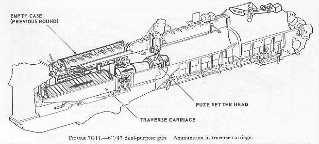 |
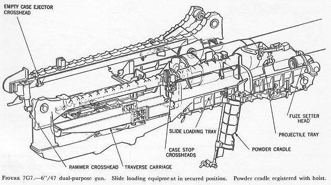
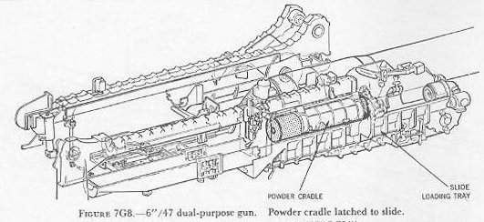
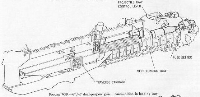
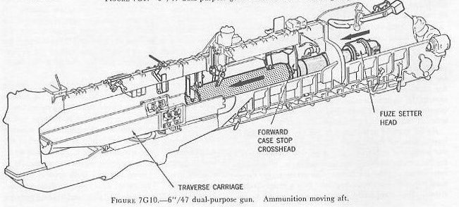
| 7G9. Turret operation This article will be concerned with ammunition supply, loading, gun firing, and extraction operations. Operations concerned with fire control, casting loose, and securing the turret will not be taken up. The student is referred to OP 760 for this information, and for further details on all aspects of this type of turret. When the ammunition hoists are filled, a powder case goes into the cradle and a projectile goes into the projectile hoist upper end. When the powder cradle receives a powder case from the hoist, it automatically rises, latches to the slide, and ejects the case into the slide loading tray (fig. 7G8). The projectile loader then manually transfers the projectile from the hoist to the slide. With both the powder case and the projectile in the slide, the projectile loader pulls down the projectile-tray control lever to start the projectile tray and fuze-setter head moving aft. The tray and fuze setter force the projectile and case to the rear of the slide against the braking action of the case stop (figs. 7G9, 7G10, and 7G11). The forward crosshead of the case stop holds the projectile nose seated in the fuze-setter head, and the fuze setter functions to set the fuze as the projectile travels aft. After the ammunition has moved all the way aft into the traverse carriage (fig. 7G11), the fuze-setter head remains in contact with the projectile fuze until the empty case from the previous round has been extracted and is latched in the empty-case tray. |
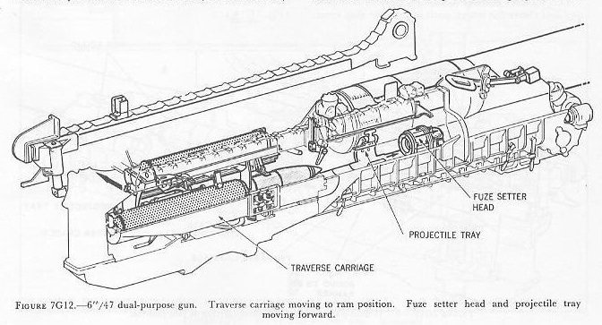 |
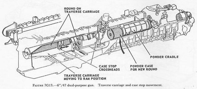
| The projectile tray and fuze setter head then move forward, clearing the traverse carriage (fig. 7G12). This allows the traverse carriage to start toward ram position. The traverse carriage continues toward ram position and clears the return path of the case-stop crossheads which were pushed to the rear by the rearward movement of the ammunition. The powder cradle, during the previous ammunition movements, has received another case, raised it, and latched to the slide ready for the next cycle. As the traverse carriage reaches ram position, the projectile tray is forward and the case stop is nearing its forward position. (Fig. 7G13.) The projectile, being manually loaded, may or may not be in the tray at this instant. The rear case-stop crosshead, upon reaching its forward position, initiates the powder-case ejection from the cradle to the slide loading tray. (Fig. 7G14.) |
 |
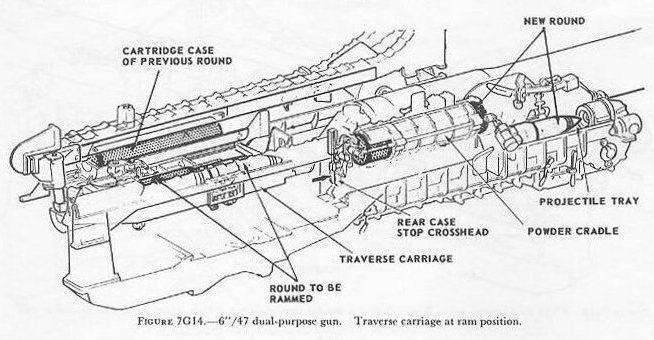 |
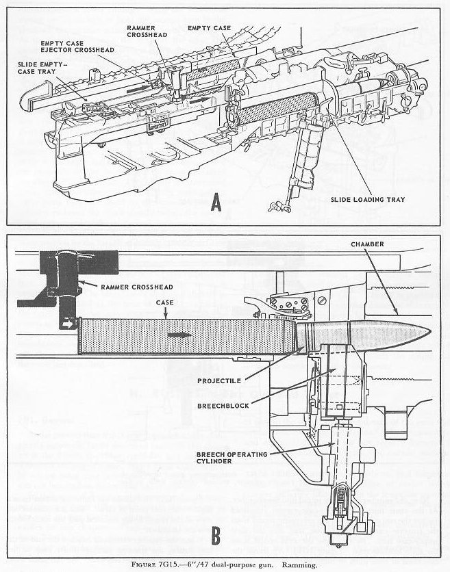
| Next, the rammer drives the round into the chamber. At the same time, the empty-case ejector crosshead pushes the empty case from the preceding round from the traverse carriage empty-case tray into the slide empty-case tray. By this time the next round is on the slide loading tray. Figure 7G15 (A) shows the operation of slide units in ramming. Figure 7G15 (B) shows the ramming action from a slightly different point of view. This is a cross-section view of the round being rammed past the breechblock into the chamber. |
 |
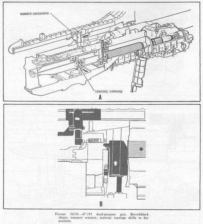
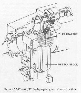
| When the rammer crosshead reaches the end of the ram stroke, the traverse carriage shifts back to fire position. See figure 7G16 (A). At the same time, the breechblock starts closing. When the block has moved up far enough to hold the ammunition in the chamber, the rammer retracts. See figure 7G16 (B). As the breechblock rises, the slope of the ways and guides in which it moves wedges the case securely in the chamber. When the breechblock has risen to its fully closed position, it is locked by the breech bolt (not illustrated), and the firing pin of the cocked firing mechanism contacts the primer of the powder case. The gun ordinarily fires electric-primed ammunition; the only percussion primers used are those in short cases for clearing the gun. When the gun fires, it moves in recoil and counterrecoil (the two strokes require about 0.5 second altogether) under the control of the recoil brake and recuperator mechanism, which are generally similar in principle to those described elsewhere in this course. During the counterrecoil stroke the breechblock is mechanically unlocked; a valve ports hydraulic fluid to the breech operating cylinder to lower the block shortly before the end of the counterrecoil stroke. When the breechblock is hauled down to its fully open position by the breech operating cylinder, it cams open a valve that activates the extractor cylinder; the fired case is extracted from the chamber (fig. 7G17) and is thrown aft into the traverse carriage empty-case tray. At the same time the gas-ejector valve is cammed open. The breechblock then rises slightly to the position it had at the time of loading, camming the extractor cylinder valve to permit the extractor to return to its seated position. The gas-ejector valve is automatically closed by a timing arrangement as the breechblock rises to loading position. The same linkage also actuates an interlock to permit repetition of the cycle just described. The fired case remains in the traverse carriage empty-case tray until the next round is rammed. See figures 7G14 and 7G15 (A). Then it is pushed forward by the case-ejector crosshead into the slide empty-case tray. Then comes the last manual operation in the gun’s operating cycle: The hot-case man picks up the case from the slide empty-case tray and drops it into a power-driven conveyor (not illustrated) called the empty-case ejector, which sends the empty out through a door in the rear of the turret. |
 |
 |