| GENE SLOVER'S US NAVY FIRE CONTROL PAGES NAVAL ORDNANCE AND GUNNERY VOLUME 2 FIRE CONTROL Appendix F STANDARD FIRE CONTROL SYMBOLS |
 |
 |
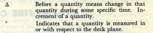
| The (triangle) as it should show up, and it's definition. The prime as it should show up, and it's definition. |
| The Greek letter, a triangle, does not show up correctly on a web page unless it is in a picture as shown above. Therefore in the text that I write, I write it out as, (triangle). In the Fire Control formula's, diagrams, and pictures that I post you need to understand the diffeerence, and why it shows up as it does. The Prime modifier, shown above, shows up in the text as ('), not as in the above picture, for the same reason. |
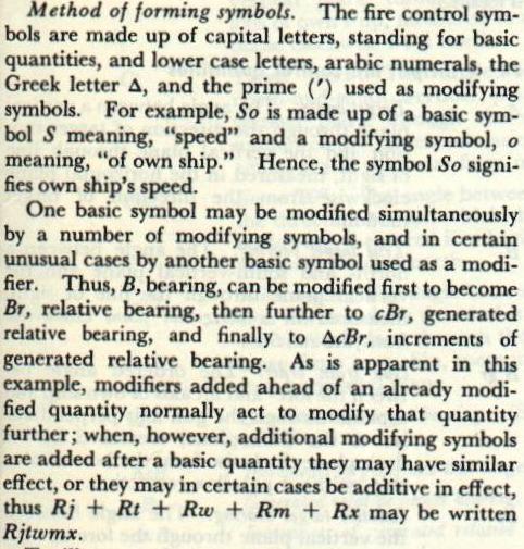
| Fl. General Symbols are used in fire control to provide a brief, accurate means of representing quantities which would otherwise require extended definition. The standard system of fire control symbols approved by the Bureau of Ordnance is applicable to the surface and antiaircraft problems and, with certain exceptions, to the torpedo fire control problem and the antisubmarine fire control problem. Standard symbols used in the torpedo fire control problem are listed in chapter 27. Method of forming symbols. The fire control symbols are made up of capital letters, standing for basic quantities, and lower case letters, arabic numerals, the Greek letter (triangle), and the prime (’) used as modifying symbols. For example, So is made up of a basic symbol S meaning, “speed” and a modifying symbol, o meaning, “of own ship.” Hence, the symbol So signifies own ship’s speed. One basic symbol may be modified simultaneously by a number of modifying symbols, and in certain unusual cases by another basic symbol used as a modifier. Thus, B, bearing, can be modified first to become Br, relative bearing, then further to cBr, generated relative bearing, and finally to (triangle)cBr, increments of generated relative bearing. As is apparent in this example, modifiers added ahead of an already modified quantity normally act to modify that quantity further; when, however, additional modifying symbols are added after a basic quantity they may have similar effect, or they may in certain cases be additive in effect, thus Rj + Rt + Rw + Rm + Rx may be written Rjtwmx. To illustrate the use of the prime, B is the basic symbol for bearing. Unmodified, it means true bearing, measured from a vertical plane through the north-south axis to a vertical plane through the line of sight to the target, in the horizontal plane clockwise from north. (Note that to define an angle completely, it is necessary to indicate (1) from what plane it is measured, (2) to what plane it is measured, and (3) in what plane it is measured.) Br, relative target bearing, is measured from a vertical plane through the fore-and-aft axis of own ship from the bow of own ship to a vertical plane through the line of sight, in the horizontal plane clockwise from the bow of own ship. Since guns and directors are fastened to the deck of the ship, they can measure Br only at that instant when the deck is horizontal. Consequently, actual values of director train (an angle measured in the deck plane is called, in fire control language, train not bearing) include a prime (’) signifying that the quantity is measured with respect to the standard reference plane of the ship, or deck plane. B’r, director train, is the quantity actually used in some dual-purpose fire control systems, and is the angle measured from the vertical plane through the fore-and-aft axis of own ship to the vertical plane through the line of sight, in the deck plane clockwise from the bow of own ship. This measurement is possible only in systems which have stabilization of the director optics, so that the cross-wires of the telescopes are maintained in the vertical and horizontal. If this is not the case, director train is measured with respect to director sights which elevate in a plane perpendicular to the deck, and the symbol is B’r’, the first prime indicating “in the deck plane,” the second prime indicating “perpendicular to the deck plane.” In the same way, E is elevation measured in a vertical plane and E’ is elevation measured in a plane perpendicular to the deck. |
| F2. Basic symbols and definitions Symbol Definition A Target angle. B Bearing (of target, unless modified), measured in the horizontal plane. C Course, measured in the horizontal plane. D Lateral deflection (angular measure). E Elevation (of target, unless modified), measured in the vertical plane. F Fuze setting. G Gyro angle (torpedoes). H Height of target (normally in feet). I Angle of climb or dive (inclination). K (Also KI, K2, etc.) Constants. L Level angle, measured in the vertical plane. M Roll. N Pitch. P Parallax. Q Spread gyro angle (torpedoes). R Range. S Speed. T Time. U Average projectile velocity. V Elevation prediction. (Angular measure.) W Wind. X Horizontal deflection component of velocity perpendicular to the vertical plane through the line of sight. Y Horizontal range component of velocity in the vertical plane through the line of sight. Z Crosslevel angle. F3. Common modifying symbols and definitions a Of torpedo. b Of director. c Before a quantity means the value of that quantity as generated by the mechanism, as opposed to the observed value of the same quantity. After a quantity means relative to rate control. d Before a quantity means a time rate of change of that quantity. After a quantity means in or relative to the deck plane or plane perpendicular to the deck. e Elevation. f Due to standard trajectory. g Of gun. h Horizontal projection of. i Searchlight (illumination). j Before a quantity means a correction or partial correction to that quantity, usually generated by the mechanism. After a quantity means arbitrary correction (spot) to that quantity. m Change of initial velocity. o Own ship; of or due to. p Parallax; of or due to. q Relative to the line of sound (ASW term). r Relative to own ship. s Relative to the line of sight, or in a slant plane. (Since several slant planes may be used, each definition specifies the plane used.) t Of or due to target. u Of torpedo tube. v Vertical projection of. w Of or due to wind. z Of or due to crosslevel. f ( ) Function of the quantity in parentheses. (triangle) Before a quantity means change in that quantity during some specific time. Increment of a quantity. ' Indicates that a quantity is measured in or with respect to the deck plane. 2 After a quantity indicates that it is the predicted value of that quantity for advance position, i. e., for the position at time of flight seconds after firing, or at time of impact or burst. 3 After a quantity indicates that it is the predicted value of that quantity for the time of the burst, of a fuzed projectile, the fuze having been set dead time seconds before firing. Note: In definitions when the terms “deck plane” or “plane of the deck” are used, the standard reference plane of the ship is meant. F4. Principal fire control quantities A Target angle. The angle between a vertical plane through the direction of target motion and the vertical plane through line of sight, measured in the horizontal plane clockwise from the direction of target motion. B True target bearing. The angle between a north- and south-vertical plane and the vertical plane through the line of sight, measured in a horizontal plane clockwise from the north. B'gr Gun train order. The ordered angle between the fore- and aft axis of own ship and a plane through the gun axis perpendicular to the deck plane, measured in the deck plane clockwise from the bow of own ship, without parallax correction. Br Relative target bearing. The angle between the vertical plane through the fore-and-aft axis of own ship and the vertical plane through the line of sight, measured in a horizontal plane clockwise from the bow of own ship. B’r Director train (stabilized sight). The angle between the vertical plane through fore-and-aft axis of own ship and the vertical plane through the line of sight, measured in the deck plane clockwise from the bow of own ship. B’r’ Director train (sight not stabilized). The angle between the fore-and-aft axis of own ship and the plane through the line of sight perpendicular to the deck plane, measured in the deck plane clockwise from the bow of own ship. Bw True direction true wind. The angle between north and the direction from which the true wind is blowing, measured in a horizontal plane clockwise from north. Bwg Predicted wind angle. The angle between the direction from which the wind is blowing and the vertical plane through the line of fire, measured in the horizontal plane clockwise from the direction from which the wind is blowing. Bws Wind angle. The angle between the direction from which the wind is blowing and the vertical plane through the line of sight, measured in the horizontal plane clockwise from the direction from which the wind is blowing. Co Own-ship course. The angle between the north- and south-vertical plane and the vertical plane through the fore-and-aft axis of own ship, measured in a horizontal plane clockwise from north. Ct Target course. The angle between the north-and-south vertical plane and the vertical plane through the direction of motion of the target, measured in a horizontal plane clockwise from north. Cw Bw-180°. The angle between north and the direction toward which the true wind is blowing, measured in a horizontal plane clockwise toward north. Cws Wind angle. The angle between the direction toward which the wind is blowing and the vertical plane through the line of sight away from own ship, measured clockwise in a horizontal plane. cB Generated true target bearing. (See definition of B.) (triangle)cB Increments of generated true target bearing. cBr Generated relative target bearing. (See Br.) (triangle)cBr Increments of generated relative target bearing. cB’r Generated director train (stabilized sight). (See B’r.) (triangle)cB’r Increments of generated director train (stabilized sight). cB’r’ Generated director train (sight not stabilized). (See B’r’.) (triangle)cB’r’ Increments of generated director train (Bearing correction). cE Generated target elevation. (See E.) (triangle)cE Increments of generated target elevation. (triangle)cEb Increments of generated director elevation. (triangle)cEb= (triangle)cE+L. cR Generated present range. (triangle)cR Increments of generated present range. Dd Deck deflection (stabilized sight). The angle representing total deflection in the deck plane; it is added to director train to obtain gun train order, B’gr. Dd+B’r=B’gr and Dd=jDd+Dz. Dd’ Deck deflection (sight not stabilized). Angle representing total deflection in deck plane; it is added to director train to obtain gun train order, B’gr. Dd’=Ds+Dz. Df Drift correction. Deflection to compensate for drift of projectile, measured in the horizontal plane. Dfs Drift correction. The lateral deflection angle to compensate for drift of a projectile, measured in the slant plane through the predicted target position. Dj Deflection spot. Ds Sight deflection. Computed angle between vertical plane through line of sight and vertical plane through gun axis(neglecting parallax), measured in the horizontal or slant plane depending on system used. Dt Relative motion deflection prediction. Deflection prediction to compensate for relative motion of own ship and target during time of flight. Dw Wind deflection prediction. Deflection prediction to compensate for the effect of apparent wind on the projectile. Dz Trunnion tilt train correction. Approximate correction in gun train order to compensate for tilting of gun trunnions in crosslevel. dBr Angular bearing rate. In the horizontal plane. The time rate of change of relative target bearing. dBs Angular bearing rate in slant plane. The time rate of change of target bearing measured in the slant plane through the line of sight. dE Angular elevation rate. The time rate of change of target elevation. dH Rate of climb. The time rate of change of target height. dR Range rate. The time rate of change of range. dRh Horizontal range rate. The time rate of change of horizontal range. dRm Alteration to prediction range rate to compensate for changes in I. V. dRs Prediction range rate. Direct range rate corrected for the effect of deflection and elevation rates, and for changes in I. V. dRxe Range rate correction. Correction to prediction range rate for the effect of the deflection and elevation rates. E Target elevation (stabilized sight). The angle between the horizontal plane and the line of sight, measured in the vertical plane through the line of sight. E=Eb-L. E’ Target elevation (sight not stabilized). The elevation above the horizontal of the line of sight, measured in the plane perpendicular to the deck, through the line of sight. Eb Director elevation (stabilized sight). The elevation of the director line of sight above the deck, measured in the vertical plane through the line of sight. E’b Director elevation (sight not stabilized). The elevation of the director line of sight above the deck, measured in a plane perpendicular to the deck, through the line of sight. Eg Vertical gun elevation. The elevation of the gun above the horizontal, measured in a vertical plane through the gun axis. E’g Gun elevation order. Ordered elevation of the gun above the deck plane, measured in a plane through the gun axis perpendicular to the deck plane. E2 Predicted target elevation. F Fuze setting order. Fuze setting in seconds. H Target height. Vertical distance between the target and the horizontal plane through the director sights. jB Initial or corrective setting to generated target bearing. jBc Linear deflection rate correction. Rate control correction affecting linear deflection rate. jB’r Correction to director train for effect of deck tilt. (Refers director train to the horizontal plane, sight stabilized.) jB’r’ Correction to director train for effect of deck tilt. (Refers director train to the horizontal plane, sight not stabilized.) jDd Partial deck deflection. An intermediate value used in computing Dd. jE Initial or corrective setting of generated target elevation. jEc linear elevation rate correction. Rate control correction primarily affecting linear elevation rate. jdR Direct range rate correction. The rate control correction primarily affecting range rate. jdRh Horizontal range rate correction. Rate control correction primarily affecting horizontal range rate. jHc Rate-of-climb correction. Rate control correction primarily affecting rate of climb. jR Initial or corrective setting of generated range. jRc Linear range correction. Applied to generated range. jRm Partial range prediction to compensate for changes of initial velocity. jRx Partial range prediction to compensate for deflection exclusive of drift. jVs Partial sight angle. (Cam output.) L Level angle. The angle between the horizontal plane and the deck plane, measured in the vertical plane through the line of sight about an axis in the horizontal plane. (Positive when the deck toward the target is below the horizontal plane.) L’ Level angle. The angle between the horizontal plane and the deck plane measured in the plane perpendicular to the deck through the line of sight about an axis in the deck. (Positive when the deck toward the target is below the horizontal plane.) Lj Selected level angle. Any arbitrary selected value of level (for those systems in which the directors measure level as L.) L’j Selected level angle. Any arbitrary selected value of level (for those systems in which the directors measure level as L’.) M Roll. The instantaneous value of the angle between the reference plane and the horizontal, measured in an athwartship vertical plane. N Pitch. The instantaneous value of the angle between the reference plane and the horizontal, measured in a fore-and-aft vertical plane. Pe Elevation parallax correction for vertical base. (In main-battery systems Pv is used for this quantity.) Ph Train parallax correction for horizontal base. Pv Elevation parallax correction for horizontal base. (See note on Pe above.) R Observed present range. RdBs Linear deflection (bearing) rate. The horizontal component of relative motion between target and own ship, at right angles to the vertical plane through the line of sight. RdE Linear elevation rate. The component of relative motion between target and own ship, at right angles to the line of sight and in the vertical plane through the line of sight. Rh Horizontal range. The projection of the range on a horizontal plane. Rj Range spot. Rm Range prediction to compensate for changes in I. V. Rt Range prediction to compensate for relative motion of own ship and target. Rtg Correction in fuze range for dead time. Rw Range prediction to compensate for effect of apparent wind on projectile. Rx Range prediction to compensate for deflection exclusive of drift. R2 Advance range (or predicted range). R3 Fuze range. R2-Rtg. S Target speed. (Note: For an air target this represents the speed of an air target along a line of flight with respect to the earth.) Sh Target horizontal ground speed. The horizontal component of air target speed with respect to the earth. So Own-ship speed. The speed of own ship relative to the earth. Ss Diving speed of target. Speed along the line sight, or direct range rate. Sw True wind speed. The horizontal velocity of wind with respect to the earth. T Time. Generated by the regulated time motor. Tf Time of flight. Tg Dead time. Time in seconds between the setting of the fuze and the firing of the projectile. V Total elevation prediction. The approximate amount that target elevation changes during the time of flight. V=Vtw-Vx+ Vj. Vf Superelevation. The angle the gun must be elevated above the predicted line of sight to compensate for the curvature of trajectory in the vertical plane. Vfm Correction to superelevation for a change in I. V. Vj Elevation spot. Vs Sight angle. The angle, computed in a vertical plane, which the gun must be elevated above the line of sight or the horizontal (depending on the system) in order to hit the target when the deck is horizontal. (A correction to Vs is needed to hit the target when the trunnions are tilted.) Vt Relative motion elevation prediction. Compensates for the relative motion of own ship and target during the time of flight. Vw Wind elevation prediction. Compensates for the effect of apparent wind on the projectile. Vx Complementary error correction. Correction to elevation prediction to compensate for deflection prediction. Vz Trunnion tilt elevation correction. Correction to gun elevation to compensate for the effect of crosslevel. WrD Deflection wind rate. The component of apparent wind velocity affecting deflection prediction. WrE Elevation wind rate. The component of apparent wind velocity affecting elevation prediction. WrR Range wind rate. The component of apparent wind velocity affecting range prediction. Xo Horizontal component of own-ship velocity at right angles to the vertical plane through the line of sight. (Deflection component.) Xt Horizontal component of target velocity at right angles to the vertical plane through the line of sight. (Deflection component.) Xw Component of true wind velocity across line of sight. Xwg Horizontal component of true wind velocity, at right angles to the vertical plane through the line of fire. (Deflection component.) Xwgr Horizontal component of apparent wind velocity, across the vertical plane through the line of fire. (Deflection component.) Xwr Component of apparent wind velocity across line of sight. Yo Horizontal component of own-ship velocity in the vertical plane through the line of sight. (Horizontal range component.) Yt Horizontal component of target velocity in the vertical plane through the line of sight. (Horizontal range component.) Yw Component of true wind velocity along line of sight. Ywg Horizontal component of true wind velocity, in the vertical plane through the line of fire. (Horizontal range component.) Ywgr Horizontal component of apparent wind velocity, in the vertical plane through the line of fire. (Horizontal range component.) Ywr Component of apparent wind velocity along line of sight. Zd Crosslevel angle. Crosslevel angle measured about an axis in the deck; the angle, measured about the intersection of the plane of the deck with the vertical plane through the line of sight, between the vertical plane and a plane perpendicular to the deck through this axis. (Positive if when you face the target the right-hand side of the ship is up.) Zdj Selected crosslevel angle. Any arbitrary value of crosslevel when crosslevel is measured as indicated in the main symbol. Zh Crosslevel angle. Crosslevel angle measured about an axis in the horizontal; the angle, measured about the intersection of the horizontal plane with the vertical plane through the line of sight, between the vertical plane and a plane perpendicular to the deck through this axis. (Positive if when you face the target the right-hand side of the ship is up.) Zhj Selected crosslevel angle. Any arbitrary value of crosslevel when crosslevel is measured as indicated in the main symbol. |