Reduction Gears and Related Equipment
In order to understand the care and operation of propulsion reduction gears, the engineer officer should be familiar with the general principles of gear design. The manufacturers of the different gears in use in the naval service have issued technical manuals, which should be thoroughly studied. The engineer officer should also be thoroughly familiar with the detailed plans of the gears which may be included in the engineering drawings furnished the ship. It is the responsibility of the engineer officer to ascertain that the required manuals and drawings for the specific equipment are on board.
This chapter contains information on the operation, care, and maintenance of reduction gears found on Navy ships. It also includes information on related equipment such as bearings and shafting. Additional details concerning a specific reduction gear installation can be obtained from the manufacturer’s technical manual.
Reduction Gears
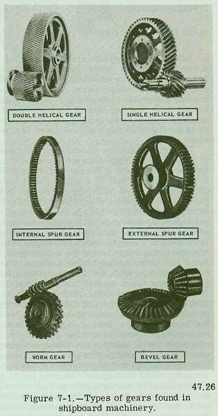
Figure 7-1 illustrates some of the more common types of gears found in various shipboard machinery. Probably one of the simplest types of reduction gearing is the worm gear, found in auxiliary machinery. Single and double helical gears are found on ships with more complicated types of propulsion machinery.
Steam turbines must operate in a relatively high rpm range for greatest efficiency while propellers operate most efficiently in a relatively low rpm range. One means of accomplishing the necessary stepdown from high turbine shaft rpm to lower propeller shaft rpm is by use of an electric drive. The most common means of obtaining the required propeller rpm for ship propulsion is by use of reduction gears.
The use of reduction gears is by no means limited to ship propulsion. Other steam turbine-driven machinery such as ship’s service generators, air compressors, and various pumps also have reduction gears. In these, as in ship propulsion units, turbine operating efficiency requires a higher rpm range than that suitable for the driven unit.
The construction, operation, and minor maintenance of main reduction gears, used with propulsion turbines and reduction gears used on auxiliary turbines, will be discussed in the following paragraphs.
Main Reduction Gears
Most main propulsion reduction gearing in current combatant ships has double helical gears (fig. 7-1). The use of double helical gears produces a smoother action of the reduction gearing and avoids tooth shock. Since the double helical gear has two sets of teeth at complementary angles to each other, end thrust, such as is developed in single helical gears, is eliminated.
Reduction gears are classified by the number of steps used to bring about the speed reduction and the arrangement of the gearing. Where only a pair of gears, that is a small gear (pinion) driven by the input shaft, drives a large (bull) gear on the propeller shaft directly, we have a SINGLE REDUCTION GEAR. In this type of arrangement, the ratio of speed reduction is proportional to the diameter of the pinion and the gear. For example, in a 2 to 1 single reduction gear, the diameter of the driven gear is twice that of the driving pinion; and in a 10 to 1 single reduction gear, the diameter of the driven gear is ten times that of the driving pinion.
Most ships built since 1935 have DOUBLE REDUCTION PROPULSIONS GEARS. In this type of gear set, a high speed pinion, connected to the input shaft by a flexible coupling, drives an intermediate (first reduction) gear which is connected by a shaft to the low speed pinion which in turn drives the bull gear (second reduction) mounted on the propeller shaft. Thus, for example, a 20 to 1 speed reduction might be accomplished by having a ratio of 2 to 1 between the high speed pinion and the first reduction gear, and a ratio of 10 to 1 between the low speed pinion on the first reduction shaft and the second reduction gear on the propeller shaft (6000 2 = 3000 10 = 300).
For a typical example of a double reduction gear application, consider the main reduction gear installation on a DD-692 class destroyer:
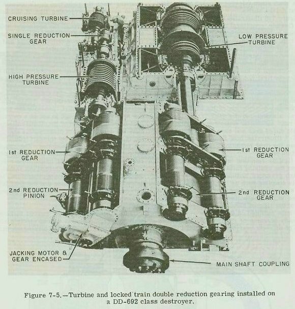
The cruising turbine is connected to the high pressure turbine through a single reduction gear. The cruising turbine rotor is solidly attached to a pinion which drives the cruising bull gear; the cruising bull gear is connected to the high pressure turbine shaft by a flexible coupling. The cruising turbine rotor and pinion are supported by three bearings, one at the forward end of the turbine and one on each end of the pinion in the cruising reduction gear case.
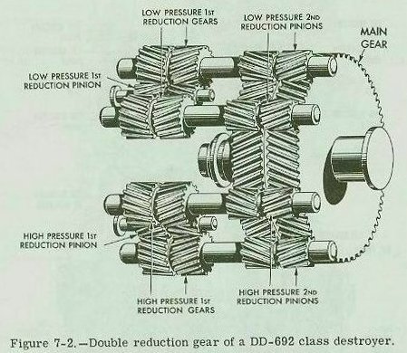
The high pressure and low pressure turbines are connected to the propeller shaft through a locked train type of double reduction gear (fig. 7-2). First reduction pinions are connected by flexible couplings to the turbines. Each of the first reduction pinions drives two first reduction gears. Attached to each of the first reduction gears by a quill shaft and flexible couplings is a second reduction (slow speed) pinion. These four pinions drive the second reduction (or bull) gear which is attached to the propeller shaft.
Types of Double Reduction Gears
The DD-692 class destroyers have a LOCKED TRAIN GEARING. There are two other arrangements of double reduction gearing in use-the ARTICULATED GEARING and the NESTED GEARING.
 ARTICULATED
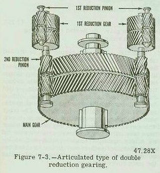
. -Typical articulated propulsion reduction gears (fig. 7-3) have two first reduction pinions (high speed), two first reduction gears, two second reduction pinions (slow speed), and a main gear. The first reduction pinions are connected to their respective turbines by flexible couplings. The first reduction gears are usually connected to the second reduction pinions by a shaft which passes through the bores of the pinions and gears and is coupled, at one or both ends, by a flexible coupling.
The articulated type of gearing generally has more bearings and occupies more longitudinal space in a ship than the nested or locked train double reduction gearing.
 NESTED
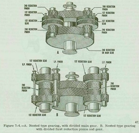
. -The nested gearing is the simplest of all double reduction gears. Nested double reduction gearing employs no quill shafts and uses a minimum number of bearings and flexible couplings. Figure 7-4 shows two different types of nested reduction gears. Note that in part B of Figure 7-4, the helixes of the first reduction gear wheels are on separate wheels, and these wheels straddle the second reduction gear wheel.
LOCKED TRAIN. -In the locked train type of double reduction gearing (fig. 7-2), each high speed pinion meshes with, or drives, two first reduction gears and thus transmits power to two second reduction pinions. Since the power path between each first reduction pinion and the main gear is split two ways instead of one way, the load on the gear teeth under a given power condition can be designed to be considerably less than it is in other types of main reduction gearing of equivalent dimensions. For a particular power rating, locked train reduction gear units can therefore be made more compact than any of the other types of reduction gears. For this reason, high powered ships, currently used by the Navy, are equipped with locked train reduction gears.
Figure 7-5 illustrates a turbine and reduction gear installation in a DD-692 class destroyer. Most ships do not have cruising turbines and cruising reduction gears, so details will vary; but most propulsion reduction gears used on destroyer type ships follow the same general pattern. Note the size of the locked train double reduction gearing for the main turbines as compared with the size of the single reduction gearing for the cruising turbine.
Construction of Main Reduction Gears
The gears in a main reduction gear unit operate at high rotational speed and must be capable of transmitting tremendous power loads. Since even very slight unevenness of tooth contour and tooth spacing would cause the gears to operate noisily or even to fail, special precautions are taken to manufacture the gears to very close limits. The gears are cut in rooms in which the temperature and humidity are kept constant. Expansion and contraction of the gear-blank, during machining, are negligible; oxidizing, due to moisture in the air, is virtually eliminated. In addition, all gears are carefully checked for errors.
CASINGS.-The gear casing can be divided into three parts. The lower part is called the base section, or the lower case. It is used to support the bull gear, the main thrust bearing, and the upper parts of the main reduction gear. The intermediate section, called the upper case, supports the bearing housing for the intermediate speed pinions and gears, as well as the high speed pinions. The other part of the gear casing is the main cover. The cover is divided into two sections which have inspection ports. These ports are covered by easily operated hinged plates and so located that the teeth of any pinion or gear can be examined without the necessity of lifting the main cover sections.
GEARS. -Double helical type gears are capable of transmitting large power loads smoothly, and do not impart axial thrust to either the driving member or the driven member.
In most reduction gears, all pinions are completely machined out of specially heat-treated nickel-steel forgings. The gear wheels are generally of built-up construction, with the teeth cut in forged steel bands which are welded to steel webs. The first reduction gears are generally welded on their respective shafts. The bull gear is usually pressed on the shaft against a locating shaft shoulder, secured by one or
more keys and locked, with a locknut, on the shaft.
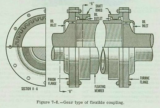
FLEXIBLE COUPLINGS.-Flexible couplings provide longitudinal and radial flexibility between the input shaft and the pinion. This permits each shaft to be adjusted axially and radially to its proper position without imposing excessive forces.
In most installations the flexible couplings are of the gear type. Power is transmitted through a floating intermediate member with external teeth that mesh with the internal teeth of the shaft rings (sleeve) mounted on the driving and driven shafts.
Figure 7-6 illustrates the design of the gear type flexible couplings that connect the main turbines to the high speed pinions of the main reduction gear. The couplings also allow for expansion of the turbine shafts, and take care of any slight misalignment between the main turbines and the reduction gears.
The design of the flexible couplings, which connect the first reduction gears and the second reduction pinion, is shown in figure 7-7. In these couplings, a quill shaft on high torsional flexibility is used, as the floating member, to obtain equal distribution of the load among the several elements of the gear train. The quill shaft runs inside the hollow bore of the intermediate speed gear and slow speed pinion.
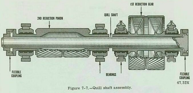
Figure 7-7 illustrates how flexibility is obtained between the first reduction gear and the second reduction pinion.
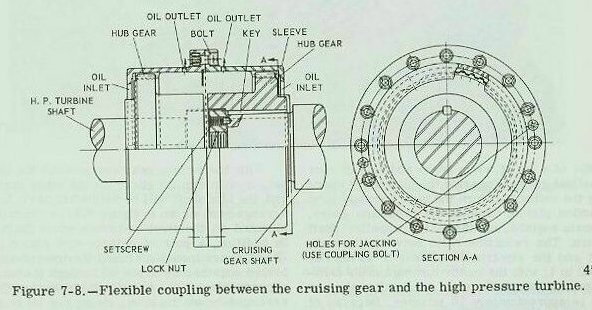
A flexible coupling is installed in the shaft between the cruising turbine reduction gear and the high pressure turbine. Figure 7-8 shows a flexible coupling such as is used on destroyers. In this coupling, the floating member is the two sleeves which are bolted together; the internal teeth of the sleeves mesh with the external teeth of the hubs mounted on the shaft.
Steady streams of oil from the supply passages of adjacent bearings are directed into the coupling when the reduction gears operate. The oil is caught by projecting lips of the turbine and pinion flanges (see fig. 7-6). Centrifugal action forces oil through the horizontal holes in the flanges to the coupling teeth. Oil is discharged from the teeth into coupling guards and then flows into the oil drain system.
In order to ensure a flooded oil condition in the area of the coupling teeth a “snap in” type of oil dam and retaining ring is provided in most couplings. Referring to figure 7-6 this dam would be placed in the shaft rings at the end of the teeth at the oil outlet. This dam provides for oil flooded coupling teeth, but it also acts as a collecting point for dirt, provided the speed of the shaft is high enough to act as a centrifuge. Dirt is centrifuged out of the oil and collects behind the dam. Frequent disassembly and cleaning is required to prevent this dirt from limiting the free action of the coupling. The couplings between the first reduction gears and second reduction pinions run at much slower speed; consequently, the dirt is flushed out rather than deposited. Frequent cleaning, therefore, is required between the turbine and the gear but not between the first reduction gears and the second reduction pinions.
TURNING GEARS.-All geared turbine installations are equipped with an electric motor-driven turning gear. A typical turning mechanism is illustrated in figure 7-9. The unit is used for turning the main engine during warming-up and securing periods so that the turbine rotor may heat or cool evenly. (The rotor of a hot turbine or of one that is in the process of being warmed up, with gland sealing steam cut in, will become bowed or distorted if left stationary even for a few minutes.) The turning gear is used for other routine purposes such as for turning the engine in order to bring the reduction gear teeth into view during routine inspection. In addition, the turning gear is used for the required daily jacking of the main engines.
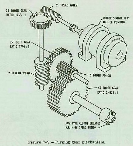
The turning gear (fig. 7-9) is mounted on top and at the after end of the reduction gear casing. A shaft, extending from the end of the high pressure first reduction pinion over the bull gear to the after end of the reduction gear casing, connects to the turning gear by means of a manually operated jaw clutch. Engaging this clutch connects the pinion to an electric motor, through a train of gears, which usually consist of a set of worm gears and sets of spur or helical gears. Engaging the clutch and operating the motor will turn the high pressure first reduction pinion, causing the reduction gears, the main engines, and the main (propeller) shaft to turn. The reduction ratio between the main shaft and the electric motor may be as high as 16,000 to 1; with the motor turning and the turning gear engaged, the main shaft will make one turn in approximately 10 minutes. Because of this high ratio, if the shaft was allowed to turn at 1 rpm, the motor would overspeed and be seriously damaged.
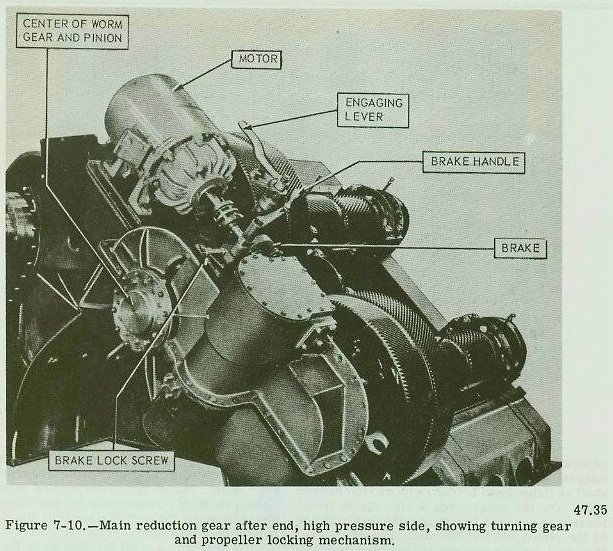
The turning gear is equipped with a propeller locking device (fig. 7-10) which is used when it becomes necessary to lock a propeller against rotation while underway. A friction brake is generally installed on the first reduction worm shaft. Either a brake drum is mounted on the worm shaft or the shaft coupling serves as a drum. (NOTE: Many locking arrangements don’t have a brake on the worm shaft.)
With the turning gear engaged and the brake set, a ship can go ahead on its other engines and the idle shaft will be held stationary. In the arrangement shown in figure 7-11, a drum (1) is mounted on the first reduction worm shaft (2). In addition, a pair of scissor-type clamp jaws (3 and 4) are mounted around the drum; they are hinged together by a pin (5) through the anchor support block (6).
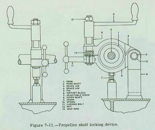
An adjustable screw (7) is arranged below the lower clamp jaw (4) to support it in such a position that, when released, the jaw will not drag on the drum. A screw shaft (8) has threads at its lower end which screw into the lower clamp jaw (4). When the crank handle (9) is turned in a clockwise direction, the screw shaft draws the upper clamp jaw toward the lower clamp jaw and tightens the jaws around the drum. This brake stops the rotation of the worm gear shaft. A spring (10) is mounted between the clamp jaws so that when the screw (8) is released, the clamp jaws are forced open; this action lifts the upper jaw and drops the lower jaw free from the drum. Another screw (11) is provided to clamp the screw (8) in either the locked or unlocked position so that accidental engaging or disengaging of the brake jaws cannot occur.
In order to engage the turning gear clutch it is necessary to first stop the shaft, either by stopping the ship or by using the astern turbine to stop and then hold the shaft stationary. The turning gear must never be engaged with the shaft turning. Regardless of how slow the shaft movement may be, damage to the motor or gears, or both, will occur. While the ship is moving the clutch should never be engaged without using the brake and continuing oil circulation to the main engine and reduction gear bearings.
Reduction Gears for Auxiliary Machinery
In the previous section of this chapter, main reduction gears of the double helix, double reduction type, were discussed. In smaller units of engineroom machinery, such as turbo-generators and turbine-driven pumps, there are different types of reduction gears.
Turbo-generators
Most ship’s service turbo-generators use a single reduction, single helix type of reduction gearing. An example of this type is found on the DD-692 class destroyers. A gear ratio of 8.3825 reduces the turbine speed of 10,059 rpm to the generator speed of 1200 rpm. The pinion is forged integral with the shaft. One end of the pinion shaft is flanged and bolted rigidly to the turbine shaft. On the other end, a high speed thrust bearing is mounted to maintain the axial position of the pinion and turbine rotor. The gear wheel is a steel forging pressed and keyed on its shaft. One end of the shaft is coupled solidly to the generator shaft, the turbine end is extended to carry the gear that drives the oil pump and governor.
Main Circulating Pumps
Turbine-driven main circulating pumps employ another type of helical gear (fig. 7-12). Single reduction, double helical gears with a ratio of about 8 to 1 reduce the turbine speed of approximately 5000 rpm to the pump speed of 600 rpm. Lubrication of the reduction gear is provided by a gear type pump mounted on the lower end of the pinion shaft. Oil is sprayed through an orifice into the space between the gear teeth.
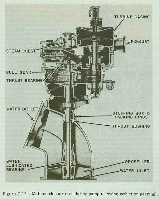
The weight of the combined rotating element of the pump and the driving unit is carried on a Kingsbury-type thrust bearing which supports a collar mounted at the upper end of the reduction gear shaft. The weight of the turbine rotor and pinion shaft is transmitted to the Kingsbury thrust bearing through the teeth of the double helical reduction gear.
The pinion is a solid forging, while the gear is constructed by welding a forged hub, forged rim, and plate sidewalls. The gear hub is bolted to a spider which is keyed to the gear shaft and held in place by the thrust collar which screws on to the shaft and locks with a setscrew.
Main Condensate Pumps
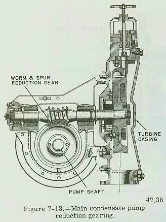
In the reduction gears used on a turbine-drive main condensate pump, shown in figure 7-13, a worm shaft and worm wheel reduce the turbine speed of 5534 rpm to the pump speed of 1145 rpm. The worm is cut in a solid, low carbon, nickel-steel forging. It is carried in two babbitt-lined split sleeve bearings and is located axially by a collar type thrust element. One end is tapered for mounting the turbine wheel while the other is squared for the application of a turning wrench.
The worm wheel is a solid, nickel-bronze casting; it is pressed on a forged steel shaft which carries the drive pinion for the speed limiting governor and the driving half of the main pump coupling. The gear casing is cast steel, specially designed to form a rigid support for the rotating elements. The gear case is of rugged construction to ensure proper alignment of the driving and driven elements, and is split horizontally to allow assembly and disassembly. The gear unit has a separate, closed pressure oil system; the bottom half of the gear casing serves as the oil sump.
Care and Operation of Reduction Gears
Some things are essential for the proper operation of reduction gears. Proper lubrication includes supplying the required amount of oil to the gears and bearings, plus keeping the oil clean and at the proper temperature. Locking and unlocking the shaft must be done in accordance with the manufacturer’s instructions. Abnormal noises and vibrations must be investigated and corrective action taken. Gears must be inspected in accordance with current instructions issued by the Naval Ship Systems Command, the type commander, or other proper authority. Information given in the sections which follow is supplementary to that given in the chapters on turbines.
Proper Lubrication of Gears
Proper lubrication of reduction gears and bearings is of the utmost importance. The correct quantity and quality of lubricating oil must, at all times be available in the main sump. The oil must be CLEAN; and it must be supplied to the gears and bearings at the pressure specified by the manufacturer. (With clean, pure oil supplied at the designed pressure and temperature, reduction gears may operate successfully for several years.)
In order to accomplish this, several conditions must be met. The lube oil service pump must deliver the proper discharge pressure. All relief valves in the lube oil system must be set to function at their designed pressure. On some ships, each bearing has a needle valve to control the amount of oil delivered to the bearing. On other ships, the quantity of oil to each bearing is controlled by an orifice in the supply line. The needle valve setting or the orifice opening must be in accordance with the manufacturer’s instructions or the supply of oil will be affected. Too small a quantity of oil will cause the bearing to run hot. If too much oil is delivered to the bearing, the excessive pressure will cause the oil to leak at the oil seal rings. Too much oil may also cause a bearing to overheat.
Lube oil must reach the bearing at the proper temperature. If the oil is too cold, one of the effects is insufficient oil flow for cooling purposes. If the oil supply is too hot, some lubricating capacity is lost. For most main reduction gears, the normal temperature of oil leaving the lube oil cooler should be between 120 F and 130 F For full power operation, the temperature of the oil leaving the bearings should be between 140°F and 160°F. The maximum TEMPERATURE RISE of oil passing through any gear or bearing, under any operating conditions, should not exceed 50°F; and the final temperature of the oil leaving the gear or bearing should not exceed 180°F. This temperature rise and limitation may be determined by thermometer or resistance temperature elements installed in the oil discharge from the bearings.
Cleanliness of lubricating oil cannot be over-stressed. Oil must be free from all impurities, such as water, grit, metal, and dirt. Particular care must be taken to clean out metal flakes and dirt when new gears are wearing in or when gears have been opened for inspection. Lint or dirt, if left in the system, will clog the oil spray nozzles. The spray nozzles must be kept open at all times. Spray nozzles should never be altered without the authorization of the Naval Ship Systems Command.
The lube oil strainers perform satisfactorily under normal operating conditions, but they cannot trap particles of metal and dirt which are fine enough to pass through the mesh. These fine particles can become embedded in the bearing metal and cause wear on the bearings and journals. These fine abrasive particles passing through the gear teeth act like a lapping compound and remove metal from the teeth.
Effects Of Acid And Water In Oil
Water and acid in oil are extremely dangerous. The oil must be tested frequently for water and at regular periods for acid. Even a small amount of water in oil can cause pitting and rusting. Fresh water can accumulate, due to leaking turbine packing glands or from condensation. Where main sump tanks are located at the skin of the ship, salt water may leak into the lube oil. Salt water may also enter through leaks in the lube oil cooler. When salt water is found in a lube oil system, corrective steps must be taken. The source of the salt water must be found and sealed off. The contaminated oil must be removed from the system by adequate flushing with clean oil.
When oil is contaminated with fresh water, adequate purification will prevent an accumulation of water in the oil but the source of water must be found and eliminated. Under normal operating conditions, operating the lube oil purifier 12 hours a day, while underway, will be sufficient; however, if the presence of fresh water is noted, the purifier will have to be operated until there is no visual indication of water in the oil and no water is discharged from the purifier. If, with additional purifier operating time, the oil does not clear up, the purifier should be checked for improper operation. The presence of salt water or fresh water in lube oil should never be ignored. The system should be checked immediately and the source of contamination should be eliminated.
When the turbines are secured, a lube oil pump should be kept running and the turning gear should be engaged and kept turning until the turbines have reached approximately room temperature (ambient). While oil is circulating, the lube oil cooler should be left in use and the purifier should be operated. Circulating oil will carry away the heat from the turbines which might otherwise reach the bearings. Operating the purifier will eliminate water caused by condensation on the interior of the reduction gear casing.
Ships should take advantage of every opportunity to have laboratory tests made of the lube oil. Samples should be tested for water, acid, and sediment content. When the neutralization number exceeds 0.50 the lube oil should be replaced.
Oil Emulsion
With continuous use, the lube oil will increase in acidity, and the free fatty acids will form mineral soaps which can form a stable oil and water emulsion. Once the emulsion has formed, the removal of water becomes more difficult, and of more importance, the oil loses its lubricating quality.
The formation of an oil film becomes impossible and the oil must be renovated. Operating with emulsified oil will result in wiped bearings and worn gear teeth.
Main Sump Oil Level
Lubricating oil is generally supplied to the gears from the main engine lubrication system, with a connection to each bearing and with nozzles located so that a constant spray of oil is directed to the gears. This constant spray of oil over the gears, not only lubricates but also cools the gears. For reduction gears, where the maximum oil level in the sump may reach the bottom of the bull gear, positive means are taken to ensure that the bull gear does not dip into the oil. An oil excluding pan is fitted around the bottom of the bull gear to prevent oil from reaching it, during normal operation.
If the gear is allowed to dip into the oil, the churning action of the gear will cause the oil to foam and to heat up. Under normal conditions, only a small quantity of oil comes in contact with the bull gear, therefore no dangerous vibration and no churning effect will occur. Oil from the gears is swept out of the pan by the bull gear and drained into the sump. A drain hole is provided on the bottom of the pan so located that drainage of any accumulated water is assured when the ship is on an even keel. When there is too much oil in the sump, the gear will churn and aerate the oil, causing a sudden increase in temperature. If this occurs, the engines must be slowed or stopped until the excess oil can be removed and normal conditions restored. Routine checks should be made to see that the lubricating oil is maintained at the proper level. Any sudden loss or gain in the amount of oil, in the main sump, should be immediately investigated.
Noises and Vibration
On steam turbine-driven ships, some noises may occur at low speeds or when maneuvering, or when passing through shallow water, which do not result from any defect in the propulsion machinery and will not occur during normal operation. A rumbling sound which occurs at low shaft rpm is generally due to the low pressure turbine gearing floating through its backlash. This condition has also been experienced with cruising reduction gears. The rumbling and thumping noises which may occur during maneuvering or during operation in shallow water, are caused by a torsional vibration initiated by the propeller. These noises referred to are characteristic only of some ships and should be regarded as normal sounds for these units. These sounds will disappear with a change of propeller rpm or when the other causes mentioned are no longer present. These noises can usually be noticed in destroyers when the ship is backing, especially in choppy seas or in ground swells.
Unusual Noises.-A properly operating reduction gear has a definite sound. At different speeds and under various operating conditions, the operator should be familiar with the normal operating sound of the reduction gears on his ship.
If any abnormal sounds occur, an investigation should be made immediately. In making an investigation, much will depend on how the operator interprets the sound or noise.
The lube oil temperature and pressure may or may not help an operator determine the reasons for the abnormal sounds. A badly wiped bearing may be indicated by a rapid rise in oil temperature for the individual bearing. A certain sound or noise may indicate misalignment or improper meshing of the gears. If unusual sounds are caused by misalignment of gears or foreign matter passing through the gear teeth, the shaft should be stopped and a thorough investigation should be made before the gears are operated again.
Vibration. -The most common causes of vibration in a main reduction gear installation are: faulty alignment, bent shafting, damaged propellers, and improper balance.
A gradual vibration in a main reduction gear that has been operating satisfactorily for a long period of time can usually be traced to a cause outside of the reduction gears. The turbine rotors, rather than the gears, are more likely to be out of balance.
When reduction gears are built, the gears are carefully balanced (both statically and dynamically). A small amount of unbalance in the gears will cause unusual noise, vibration, and abnormal wear of bearings.
When the ship has been damaged, vibration of the main reduction gear installation may result from misalignment of the turbine, the main shafting, the main shaft bearings, or the main reduction gear foundation. When vibration occurs within the main reduction gears, damage to the propeller should be one of the first things to be considered. The vulnerable position of the propellers makes them more liable to damage than other parts of the plant. Bent or broken propeller blades will transmit vibration to the main reduction gears. Propellers can also become fouled with line or cable which will cause the gears to vibrate. No reduction gear vibration is too trivial to overlook. A complete investigation should be made, preferably by a naval shipyard.
Maintenance of Main Reduction Gears
The main reduction gear is one of the largest and most expensive units of machinery found in the engineering department. Main reduction gears that are installed properly and operated properly will give years of satisfactory service. However, a serious casualty to main reduction gears, will either put the ship out of commission or force it to operate at reduced speed. Main reduction gear repairs can be very expensive as repairs usually have to be made at a shipyard. The sections which follow deal with gear teeth. Bearings are covered in a separate section.
The importance of proper gear tooth contact cannot be overemphasized. Any abnormal condition which may be revealed by operational sounds or by inspections should be corrected as soon as possible. Any abnormal condition which is not corrected will cause excessive wear which may result in general disintegration of the tooth surfaces.
If proper tooth contact is obtained when the gears are installed, little wear of teeth will occur. Excessive wear cannot take place without metallic contact. Proper clearances and adequate lubrication will prevent most gear tooth trouble.
WEAR-IN OF GEAR TEETH.-Gears which have been realigned and new gears should be given a wearing-in period at low power before being subjected to the maximum tooth pressure at full power.
TOOTH CONTACT. -For proper operation of the gears, it is essential that the total tooth pressure be uniformly distributed over the total area of the tooth faces. This uniform pressure is accomplished by accurate alignment and adherence to the designed clearance.
The designed center-to-center distance of the axes of the rotating elements should be maintained as accurately as practicable but the axes of pinions and gear shafts must always be parallel. If the shafts are not parallel, the load is concentrated on one end of a helix; the result may be flaking, galling, pitting, featheredges on teeth, deformation of tooth contour, or breakage of tooth ends.
Tooth Contour. -The designed tooth contour must be maintained. A lack of it can cause load concentrations with consequent scoring.
Backlash. -Backlash is the play between the unloaded surfaces of the teeth in mesh on the pitch circle. Backlash increases with wear, and can increase considerably without causing trouble.
Tooth Surface Wear.-If proper contact is obtained when the gears are installed, the initial wearing, which takes place under conditions of normal load and adequate lubrication, will smooth out rough and uneven places on the gear teeth. This initial wearing-in is referred to as NORMAL WEAR or RUNNING IN. As long as operating conditions remain normal, no further wear will occur.
Small shallow pits starting near the pitch line, will frequently form during the initial stage of operation; this process is called INITIAL PITTING. Often the pits (about the size of a pinhead or even smaller) can be seen only under a magnifying glass. These pits are not detrimental and usually disappear in the course of normal wear.
Pitting which is progressive and continues at an increasing rate is known as DESTRUCTIVE PITTING. The pits are fairly large and are relatively deep. Destructive pitting is not likely to occur under proper operating conditions, but could be caused by excessive loading, too soft material, or improper lubrication. It is usually found that this type of pitting is due to misalignment or to improper lubrication.
The condition in which groups of scratches appear on the teeth (from the bottom to the top of the tooth) is termed abrasion, or scratching. It may be caused by inadequate lubrication, or by the presence of foreign matter in the lubricating oil. When abrasion or scratching is noted, the lubricating system and the gear spray fixtures should immediately be examined. If it is found that dirty oil is responsible, the system must be thoroughly cleaned and the whole charge of oil centrifuged.
The term “scoring” denotes a general roughening of the whole tooth surface. Scoring marks are deeper and more pronounced than scratching and they cover an area of the tooth, instead of occurring haphazardly, as in scratching or abrasion. Small areas of scoring may occur in the same position on all teeth. Scoring which occurs with proper alignment and operation, usually results from inadequate lubrication, and is intensified by the use of dirty oil. If these conditions are not corrected, continued operation will result in a general disintegration of the tooth surfaces.
Root Clearance.-The designated root clearance with gear and pinion operating on their designed centers can be obtained from the manufacturer’s blueprints. The actual clearance can be found by taking leads or by inserting a long feeler gage or wedge. The actual clearance should check with the designed clearance. If the root clearance is considerably different at the two ends, the pinion and gear shaft will not be parallel. Provided there is still sufficient backlash, and the teeth are not meshed so closely that lubrication is adversely affected or that clearance is reduced below specified limits, the tolerance will be satisfactory.
Checking Tooth Contact.-The length of tooth contact across the face of the pinion is the means of determining if reduction gear alignment is satisfactory. To check the length of tooth contact, the teeth of one gear should be coated lightly with prussian blue (machinist’s dye) and the teeth of the other gear with yellow chromate or red lead pigment, and the gears rolled (with the turning gear) with sufficient torque to cause metal contact between the meshing teeth.
Either copper sulphate or blue or red Dykem is used to determine tooth contact for operating conditions. Dykem should be used for dock trials as it will show markings for light load conditions. Copper sulphate markings will remain visible after longer and higher power operations than will Dykem markings. Lubricating oil must be removed from the gear teeth by an approved cleaning agent, before the compound is applied; several bands should be coated on all gear elements. After the tooth contact is determined, the compound must be removed from the gear teeth to prevent possible contamination of the lubricating oil.
It should be noted that some gear teeth are cut with a very slight taper to offset the effects of torsional twist and bending. In such gearing, full contact across the teeth will not be obtained at light loads.
Spotting Gear Teeth. -Rough gear teeth should be stoned smooth if it is certain that the roughening was caused by the passage of some foreign matter. Any tooth deterioration which cannot be traced to a casualty should be investigated, giving special attention to the condition of the bearing, to lubrication, and to the possibility of a change in the supporting structure, which has disturbed the parallelism of the rotors.
To spot-in surfaces of reduction gear teeth, the pinion teeth are coated lightly with prussian blue. Then the gear is turned in its ahead direction by using the turning gear. As the gear teeth come in contact with the marked pinion teeth, an impression is left on the high part of the gear tooth. After the gear is turned 1/4 turn, or is in a convenient position for stoning, all high spots indicated by the marks are removed with a small handstone. It will be necessary to replace the bluing on the pinion teeth repeatedly, but if the bluing is applied too thickly, false impressions will be left on the teeth.
It is permissible to hand stone gear teeth, with a small oil stone, to remove a local hump or deformation, however, hand stoning of gear teeth to obtain contact is not permitted. Hand stoning to obtain contact, cannot be done without the approval of the Naval Ship Systems Command.
Maintenance of Cruising Turbine Reduction Gears
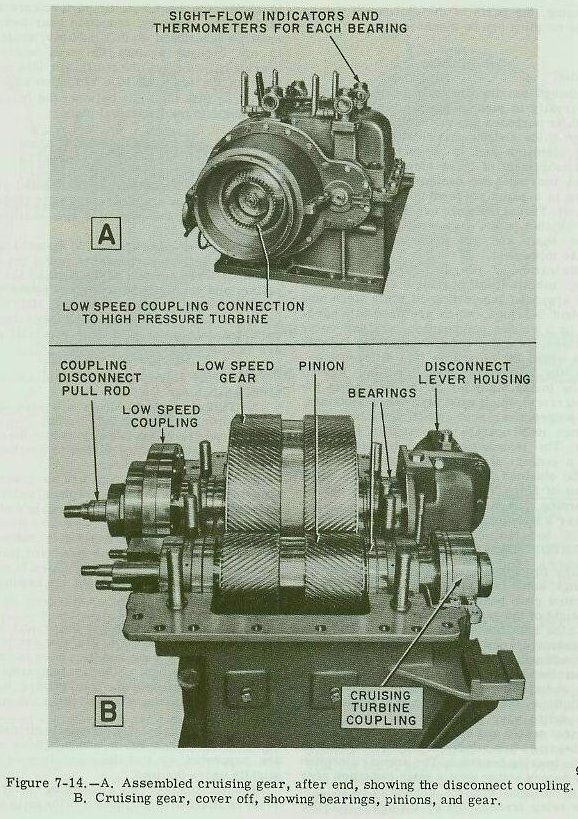
Many destroyers, as well as other type ships, have cruising turbines and cruising turbine reduction gears. These gears differ primarily from main reduction gears in that they are single reduction. This type reduction gear (fig. 7-14) consists of one pinion and one reduction gear enclosed in a housing and fitted with the necessary bearings, thermometers, oil lines, and other fittings. Detailed information concerning the construction of cruising turbine reduction gears can be obtained from the manufacturer’s technical manual for the specific installation.
Maintenance for cruising reduction gear installations is basically the same as for main reduction gears. Repair work for a cruising gear may be easier because there are fewer bearings in a cruising gear, which may mean less work if the bearings need replacing. Having only one pinion and one gear, cruising gears do not have to be timed as do main reduction gears. The casing of a cruising reduction gear is easier to lift than a main gear casing.
Bearing Maintenance
In some cruising reduction gear installations, the bearing shells are very thin and are not suitable for rebabbitting. Such bearings, if damaged, must be replaced with new bearings.
To replace cruising gear bearings, it is necessary to proceed as follows: Remove the bolts in the horizontal and vertical joints of the coupling guards. Remove the upper half of the coupling guards; the alignment bearing (centering ring) may raise with the low speed coupling guard. Remove the bolts in the vertical joint, between the disconnect lever housing and the gear casing. Remove the nuts from the bearing cap studs, these studs extend through the upper half of the gear casing. Remove all bolts from the horizontal joint of the gear casing. Lift the upper half of the gear casing; then the bearings can be removed for inspection.
Gear Tooth Maintenance
As with main reduction gear teeth, cruising gear teeth must be kept in correct alignment at all times. Uniform distribution of wear over the entire length of the gear and pinion teeth is an indication of correct contact. Any evidence of poor tooth contact is an indication of worn bearings or misalignment of the gears.
The pinion should not be removed from the assembly unless it is necessary to replace it. The pinion can be lifted by the following procedure: Remove the upper half of the reduction gear casing. Place the support yoke under the after end of the cruising turbine shaft and remove the bolts from the cruising turbine coupling. Remove the upper half of the pinion bearings. The use of hydraulic pressure, rather than pneumatic, is recommended for removing such fitted parts. However, an air fitting is installed in the cruising turbine coupling, through which air pressure can be applied to force the tapered part out of position. The pinion can now be removed. (NOTE: Extreme caution should be taken when using pneumatic pressure.)
In order to remove the gear from the assembly, it is necessary to remove the disconnect device and the coupling at the same time. After the gear has been removed from the casing, the parts of the disconnect device and the coupling can be disassembled.
Bearings
Although bearings in main propulsion units vary greatly in size, composition and lubrication, their purposes are the same. Bearings are used to guide and support rotating or reciprocating elements and to prevent free axial or radial movement of these elements. Radial or journal bearings are designed to carry loads applied in a plane perpendicular to the axis of the shaft. Thrust bearings are designed to carry loads applied in the same direction as the axis of the shaft and are used to prevent free endwise movement.
Lubrication of bearings differs. For example, babbitt-lined bearings are lubricated by an approved lubricating oil while stern tube and strut bearings, which are lined with hardwood or a rubber composition, are salt water lubricated. Bearings are designed to operate with a small oil clearance (the difference between the outside diameter of the journal and the inside diameter of the bearing is the oil clearance) which must always be maintained. With proper clearances and proper lubrication, bearings may operate successfully for many years. The information given in this section is of a general nature. Additional information may be obtained from chapter 9430 (43) of the Bureau of Ships Technical Manual. For details concerning a particular unit, consult the manufacturer’s technical manual.
Main Reduction Gear Bearings
Many propulsion gears have roller and ball bearings; some have spherical seated bearings. Reduction gear bearings must not only support the weight of the gears and their shafts, but they must also hold the shafts in place against the tremendous forces exerted by the shafts and gears when they are transmitting power from the turbine shaft to the propeller shaft. Like other radial sleeve bearings in main engine installations, these bearings are of the babbitt-lined split type; however, instead of being spherical seated and self-aligning, the reduction gear bearings are rigidly mounted, and doweled into the bearing housings. The angular direction of the forces acting upon a main reduction gear bearing changes with the amount of propulsion power being transmitted by the gear. In order to obtain the best bearing performance when load is the greatest, reduction gear bearings must be positioned so that the heavy shaft load is not brought against the area where the bearing halves meet (the split). For this reason most of the bearings in a reduction gear are placed so that the split between the halves is at an angle to the horizontal plane.
Main Thrust Bearings
The main thrust bearing is located either at the forward or after end of the main reduction bull gear or in the propeller line shafting aft of the gear.
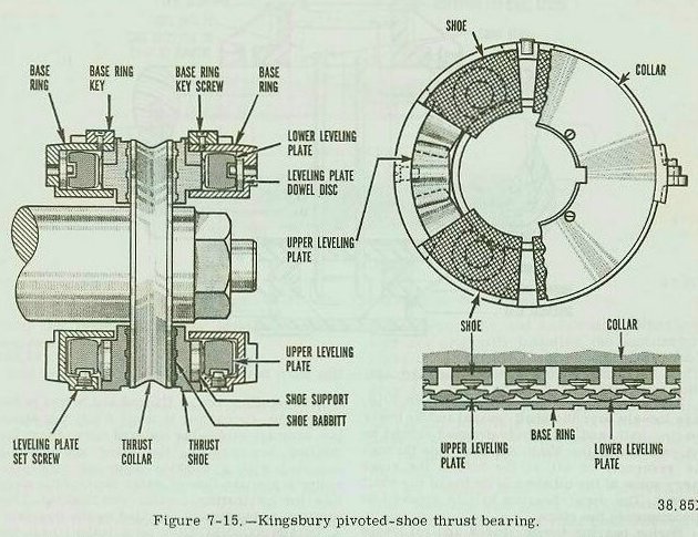
Axial or thrust bearings are mounted on the main shaft for two purposes: to resist any axial thrust or force exerted on the shaft by the propeller, and to limit the axial movement of the shaft to a small running clearance. Main thrust bearings are pivoted-segmental shoe type as indicated in figure 7-15. The essential parts are as follows:

1. Thrust collar-made of steel and keyed to the shaft.
2. Tilting segments, or shoes-made of aluminum-bronze and faced with babbitt.
3. Upper leveling plates upon which the shoes rest, and lower leveling plates to equalize the thrust load among the shoes.
4. Base ring-which supports the lower leveling plates, holds the plates in place, and transmits the thrust on the plates to the ship’s structure.
5. Shoe supports (hardened steel buttons or pivots)-forming part of the shoes and pivoting them against the upper leveling plates in such a manner that the shoe segments can assume the correct angle.
Pins and dowels hold the upper and lower leveling plates in position, allowing ample play between the base ring and the plates to ensure freedom of movement of the leveling plates. The base ring is prevented from turning by its notched construction, which secures the ring to its housing.
The stationary bearing element is divided into six or more segments or shoes. These shoes are supported so that they are free to pivot slightly under the load.
The rotating bearing element or collar (fig. 7-15) is attached to and turns with the main shaft.
The entire assembly is submerged in oil, some of which is dragged in between the collar and each shoe as the shaft rotates.
Lubrication of the main thrust bearing is provided by the same system which furnishes oil to the turbine bearings, reduction gears, and flexible couplings-if located in with the reduction gear. If the main thrust bearing is located in the shaft alley, then lubrication of the bearing differs. The bearing will have its own oil sump, oil system, oil cooler, and pumps. While turning the engines by jacking gear, backing down, or going ahead slow, oil is supplied by an electric-driven gear pump. When the shaft speed is increased sufficiently, a shaft-driven gear pump supplies oil to the bearing and the electric -driven pump is secured. The shaft speed at which the shaft-driven pump can be secured will vary with the type of ship. For additional information, consult the manufacturer’s technical manual for the specific unit or equipment.
Main Propulsion Shaft Bearings
The bearings which support and hold the propulsion shafting in alignment are divided into two general groups: the main line shaft bearings or spring bearings, and the stern tube bearings and the strut bearing.
Main Line Shaft Bearings or Spring Bearings
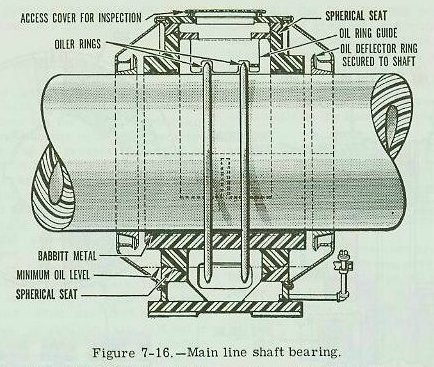
These bearings are of the ring-oiled, babbitt-faced, spherical seat, shell type. This bearing (see fig. 7-16) is designed primarily to align itself to support the weight of the shafting. On some low powered ships, the bearing is not of the self-aligning type and consists only of a bottom half. The upper half of the assembly consists only of a cap or cover (not in contact with the shaft) to protect the shaft journal from dirt. The spring bearings of most naval ships, however, are provided with both upper and lower self-aligning bearing halves.
The brass oiler rings, shown in figure 7-16, hang loosely over the shaft journal and the lower bearing half, and are slowly dragged around by the rotation of the shaft. As they glide through the reservoir of oil at the bottom the rings carry some of the oil along to the top of the shaft journal. The upper bearing half is grooved to accommodate the rings.
Spring bearing temperatures and oil levels should be checked hourly while underway. At the overhaul cycle the bearings should be inspected, clearances taken, and defects corrected.
Stern Tube and Stern Tube Bearings
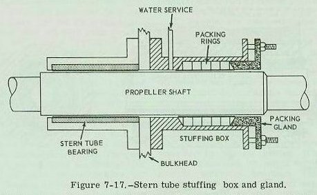
The hold in the hull structure for accommodating the propeller shaft to the outside of the hull is called the stern tube. The propeller shaft is supported in the stern by two stern tube bearings-one at the inner end and one at the outer end of the stern tube. At the inner end of the stern tube is a stuffing box packing gland (fig. 7-17) generally referred to as the stern tube gland. The stern tube gland seals the area between the shaft and stern tube and yet allows the shaft to rotate. Construction of the stern tube bearings is similar to that of the strut bearings. (See the next section of this chapter.)
The stuffing box is flanged and bolted to the stern tube. Its casting is divided into two annular compartments-the forward space being the stuffing box proper, the after space being provided with a flushing connection for providing a positive flow of water through the stern tube for lubricating, cooling, and flushing. This flushing connection is supplied by the firemain. A DRAIN CONNECTION or a leakoff past the packing (on natural pressure circulation systems) is provided both for testing the presence of cooling water in the bearing, and for permitting sea water to flow through the stern tube and cool the bearing when the ship is underway, where natural sea water circulation is employed.
The gland for the stuffing box is divided longitudinally into two parts. The gland bolts are long enough to support the gland when the latter is withdrawn at least 1 inch clear of the stuffing box. This permits the addition of a ring of new packing, when needed, while the ship is waterborne. Either braided flax packing or special semimetallic packing is used (ship’s engineering drawings show the proper type of packing). This gland is usually tightened up to eliminate leakage when the ship is in port, and loosened just enough to permit a slight trickle of water for cooling purposes, when the ship is underway. (NOTE: On anchoring, the glands of natural pressure circulation systems should NOT be disturbed unless leakage becomes excessive.)
Strut Bearings
These bearings, as well as the stern tube bearings, are equipped with composition bushings which are split longitudinally into two halves. The outer surface of the bushing is machined with steps to bear on matching landings in the bore of the strut. One end is bolted to the strut.
Since it is usually impracticable to use oil or grease as a lubricant for underwater bearings, some other material must be employed for that purpose. There are certain materials that become slippery when wet, including natural or synthetic rubber; lignum vitae, a hard tropical wood with excellent wearing qualities; or laminated phenolic material consisting of layers of cotton fabric impregnated and bonded with phenolic resin. Strips of this material, as shown in figure 7-18, are fitted inside the bearing.
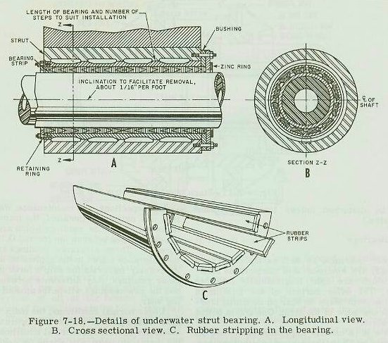
A rubber composition is the type most used in modern installations. These bearings, of course, will never be seen while the ship is afloat, and chances are when the ship is in dry-dock, the naval shipyard personnel will perform the required work. However, the engineer officer should check the bearings visually.
Care of Bearings
Properly operated bearings may give years of satisfactory service but like all units of engine room machinery, they require periodic tests, inspections, and maintenance. When bearings are originally installed, the manufacturer takes oil clearance readings which are usually the differences between the journal O.D. and the bore I.D. These clearance readings are within the tolerance shown in the applicable drawings. At regular intervals the ship’s force must take these readings. Any difference between the old and the new readings will be the amount of bearing wear.
Under normal conditions, the main reduction gear bearings and gears will operate for an indefinite period. If abnormal conditions occur, the naval shipyard will normally perform the repairs. Sufficient repair parts are carried aboard to replace some bearings installed in the main reduction gear. Usually each bearing is interchangeable for the starboard or port installation. The manufacturer’s technical manual must be checked for interchangeability of gear bearings.
Special tools and equipment needed to lift main reduction gear covers, to handle the quill shaft when removing bearings from it, and to take required readings and measurements, are normally carried aboard. The special tools and equipment should always be aboard in case emergency repairs have to be made by repair ships or bases not required to carry these items.
Journal Bearings.-A bearing, used in reduction gears, has a pressure half and a non-pressure half, when referring to the ship’s going ahead. The non-pressure half will usually have a radial scribe line at one end of the geometric center. The pressure half of all main reduction gear bearing shells usually has three radial scribe lines on each end. These bearings are all marked for crown thickness measurements. The crown thickness is measured approximately 1 1/4 inches from the end of the shell. These measurements are taken and recorded at the initial alignment and are permanently marked adjacent to each scribe line. Directions for reboring are generally marked on those bearings which are designed to be rebabbitted.
The amount of bearing wear allowed should not be great enough to allow incorrect gear tooth contact. The designed bearing clearances and wear data are generally given in the manufacturer’s technical manual. These clearances and wear data are also given in the blueprints for the main reduction gears. The maximum allowable clearance can be determined by referring to the Bureau of Ships Technical Manual, chapter 9430 (43).
Replacing bearings in the main reduction gear is a major undertaking. When a casualty (such as the loss of lube oil) occurs, the high speed pinion shaft bearings are more likely to be wiped than the other main gear bearings. These high speed pinion shafts (coupled to the high pressure and low pressure turbines) will have a higher rotary speed than other shafts in the reduction gear. If the bearings are inspected, the high speed pinion bearings should be checked first. The bearings which rotate at lower speeds are normally not wiped. If repairs are to be made by the ship’s force, personnel should refer to the manufacturer’s technical manual and the blueprints for the reduction gear. A clear understanding of the construction details and repair procedure is most helpful before starting a repair job. Some factors to be considered in determining where repairs are to be made include: location of the ship, available repair facilities, available repair parts, and the operating schedule of the ship. In making repairs, the first step is to engage the turning gear and set the brake to ensure that the shaft will not turn while repairs are being made. All oil must be pumped out of the main sump tank. A clean settling or storage tank can be used to store the oil until it is ready for use again. Then a section of the reduction gear cover is lifted by using chain-falls and wire slings. (NOTE: On some installations, journal bearings can be replaced without lifting covers.) When the gear cover is moved out of the way, the bearing cover can be removed. Next the bearing must be turned so that the bearing split is on the horizontal plane and the top half of the bearing can be lifted off. The gear shaft must be supported when the bottom half of the bearing is removed. A dummy, or similar device, bearing is used to support the weight of the shaft and to keep the shaft in position. Special precautions should be taken to prevent the shaft from being turned or lifted, so that the gear teeth do NOT become unmeshed. If the gear teeth become unmeshed and are not match marked, it is necessary to follow a complicated and detailed procedure to reassemble and time the gears. The setting up of the locked train gear system is done at the factory and at naval shipyards.
If the bearing has excessive clearance, is badly wiped, or heavily scored, other representative bearings should be examined to determine the extent of the damage. All bearings on that particular shaft, should be replaced, if necessary, to maintain correct gear alignment.
To replace a bearing, proceed as follows:1. Review the Material History to determine if special bearings are necessary.
2. Measure the diameter of the journal (with a micrometer) and compare the present readings with the original readings, as recorded in the Material History.
3. Check the crown thicknesses of installed and replacement bearings and compare readings. If scraping is required for the replacement bearing, use a full-sized mandrel and prussian blue to check the work. Shaft parallelism must be maintained.
4. To maintain shaft parallelism, bearings on the ends of gear or pinion shafts shall not differ in crown thickness more than 0.002 inch.
5. When a bearing is installed or a damaged bearing is scraped to maintain correct tooth contact, the crown thickness shall be stamped on the bearing shell.
6. Dowels are used, between the bearing halves, to locate the bearings in the upper casing. Upper and lower bearing halves must be mated parts. Interchanging of upper and lower bearing halves is prohibited.
7. Examine the condition of the journal whenever bearings are removed. If the surface of the journal is slightly scored, it must be stoned and polished. Only experienced personnel should stone a journal. Always oil a journal before rolling in a new bearing.
NOTE: If journals are badly scored, they may be ground undersize or restored to design diameter by chrome plating. If a journal is ground undersize, it might be necessary to provide undersize bearings. This should be accomplished only by a naval shipyard and in accordance with existing instructions. The new journal diameters and bearing clearances must be recorded in the Material History.
When installing a bearing, make sure that it is well oiled, then roll the lower half into position, removing the dummy bearing. The upper half can be placed in position, and then the complete bearing can be shifted to its proper position. Ensure that the dowels are in place and that the bearing assembly is in its required position, in accordance with the manufacturer’s instructions. The bearing cap can be lowered into position and securely bolted down.
Before the gear cover is lowered into position, a careful inspection should be made to see that the inside of the gear installation is free of all dirt, tools, rags, and other foreign matter that would be harmful to the gears. After the gear cover is lowered into position and bolted down, the lube oil can be pumped to the sump. Before the oil is circulated through the system, MUSLIN bags should be placed in oil strainers. The muslin bags will trap any dirt or foreign matter that is too fine to be stopped by the strainer. A lube oil service pump should be started to circulate oil through the system. The muslin bags should be changed at 30-minute intervals until they no longer pick up dirt. The turning gear can then be engaged and started.
Thrust Bearings.-This section contains only general information on different methods of taking end play readings on the main thrust bearing. See the manufacturer’s technical manual for specific information on any given unit.
Checking the end play for any six-or eight-shoe thrust bearing must always be done with the top half of the bearing bolted down solidly, otherwise the base rings will tilt because of the freedom of movement given the leveling plates, and a false reading will be obtained.
A record of the main thrust readings must be kept in the Material History and referred to when checking the main thrust bearing. Over a period of years, the normal wear of a pivoted-shoe thrust bearing is negligible. However, when the bearing is new, there may be a slight settling of the leveling plates. Any increase in the end play of a main thrust bearing indicates the surfaces of the thrust shoes should be inspected, and necessary repairs made.
In many main thrust bearings, a port is provided (in the main thrust bearing cap over the thrust shoes) for inspection purposes. This port has a removable cover of sufficient size to permit the withdrawal of thrust shoes that are in line with it.
Checking Thrust While Underway.— The simplest means of checking end play is to use a dial indicator on any accessible flange on the main shaft while the engines are going slowly ahead and then astern. This can usually be done when the ship is maneuvering to approach a pier or an anchorage. The speeds should be slow enough to avoid adding deflections of bearing parts and housing to the actual end play. But, the speed should be sufficient to ensure that the full end play is actually taken up.
Some ships have the main thrust bearing located at the forward end of the main reduction gear, and constructed as a component part of the gear. A spring-loaded pin gage (located in the bearing end cover housing) and a micrometer depth gage are used to measure the end play. The pin gage cover is removed and the anvil of the depth gage is placed on the machined surface of the pin gage housing. The micrometer is carefully turned so that the spindle pushes the installed pin against the main shaft. All slack must be taken up; but excessive force must not be used, as it will lift the micrometer anvil from the machined surface.
Another reading is taken with the main shaft operating in the opposite direction. The difference between the two readings is the end play. It is always good practice to take more than one set of readings to ensure that the total end play was taken up and that the readings are accurate.
Jacking on a Shaft Flange.—If it is not practical to measure the end play while running, the next choice is to jack the shaft (while it is still warm) fore and aft at some convenient main shaft flange. A dial indicator is mounted on a rigid support, convenient to some main shaft flange and the shaft is jacked forward and then astern. The shaft movement must be free; too great a force should not be used. Excessive force might cause deflections of metal parts to be added to the actual end play. The main difficulty in using the jacking method is finding suitable supports where no structural damage will be done.
Propellers and Main Propulsion Shafting
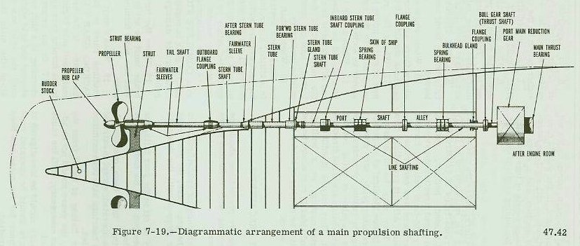
The turbine and reduction gears convert the thermal energy of steam into usable mechanical energy. This mechanical energy is utilized through the propulsion shafting and the propeller. The Main Propulsion Shafting, which ranges in diameter from 18 to 21 inches for small twin-screw destroyers to approximately 30 inches for large four-screw carriers, is divided into four functional sections-the line shaft, thrust shaft, stern tube shaft, and propeller or tail shaft (fig. 7-19).
Main Propulsion Shafting
Segments of the line and thrust shaft sections of the shafting are joined together with integral FLANGE TYPE COUPLINGS. The stern tube shaft is joined to the after end of the line shaft with what is known as the INBOARD STERN TUBE COUPLING, with a removable after-sleeve flange. The tail shaft is joined to the stern tube shaft with what, is known as a MUFF TYPE OUTBOARD COUPLING. The shaft bearings have already been discussed in a preceding section.
On single-screw ships, that portion of the outboard shaft which turns in the stern tube bearing is normally covered with a SHRUNK-ON COMPOSITION SLEEVE. This is done to protect the shaft from corrosion, and to provide a suitable journal for the water lubricated bearings. On multiple-screw ships, these sleeves normally cover only the bearing areas, and the exposed shafting between the sleeves is covered with synthetic sheet rubber to protect it against sea water corrosion.
For carriers ‘and cruisers, normally the wet shafting (shafting outboard in the sea) is composed of three sections, a tail shaft, an intermediate or dropout section, and a stern tube section. Integral flanged ends of these sections are normally used for joining sections together.
Propellers
The screw propellers, where the mechanical energy produced by the main engine is finally utilized, are of various types of construction. They may be left-handed helices, turning counterclockwise in ahead direction when viewed from astern, or right-hand helices, turning clockwise. All starboard and centerline propellers turn clockwise. All port propellers turn counterclockwise. They may be of constant pitch, with pitch of blades identical at all points along the radius; variable pitch, with pitch of blades varying along the radius; or controllable pitch, with blades capable of being rotated within their sockets to change speed and direction of propeller thrust. They may be of solid construction, of single casting, or a built-up construction with individually cast blades bolted to the propeller hub. The number of blades may vary from three to seven.
Safety Precautions
The following safety precautions should be observed when working with reduction gears and related equipment:
1. If there is churning or emulsification of oil and water in the gear case, the gear must be ‘slowed down or stopped until the defect is remedied.
2. If the supply of oil to the gear fails, the gears should be stopped until the cause can be located and remedied.
3. When bearings have been overheated, gears should not be operated, except in extreme emergencies, until bearings have been examined and defects remedied.
4. If excessive flaking of metal from the gear teeth occurs, the gears should not be adjusted, except in an emergency, until the cause has been determined.
5. Unusual noises should be investigated at once, and the gears should be operated cautiously until the cause for the noise has been discovered and remedied.
6. No inspection plate, connection, fitting, or cover which permits access to the gear casing should be removed without specific authorization by the engineer officer.
7. The immediate vicinity of an inspection plate should be kept free from paint and dirt.
8. When gear cases are open, precautions should be taken to prevent the entry of foreign matter. The openings should never be left unattended unless satisfactory temporary closures have been installed.
9. Lifting devices should be inspected carefully before being used and should not be overloaded.
10. When ships are anchored in localities where there are strong currents or tides, precautions should be taken to lock the main shaft.
11. Where the rotation of the propellers may result in injury to a diver over the side, or in damage to the equipment, propeller shafts should be locked.
12. When a ship is being towed, the propellers should be locked, unless it is permissible and advantageous to allow the shafts to trail with the movement of the ship. When the shaft is locked, lube oil must be supplied to the propulsion machinery.
13. When a shaft is allowed to turn or trail, the lubrication system MUST be in operation. In addition, a careful watch should be kept on the temperature within the low pressure turbine casing to see that windage temperatures cannot be built up to a dangerous degree. This can be controlled either by the speed of the ship or by maintaining vacuum in the main condenser.
14. The main propeller shaft must be brought to a COMPLETE STOP before the clutch of the turning gear is engaged. (If the shaft is turning, considerable damage to the turning gear will result.)
15. When the turning gear is engaged, the brake must be set quickly and securely to prevent the shaft turning and damaging the turning gear.
16. When a main shaft is to be unlocked, precautions must be taken to DISENGAGE THE JACKING GEAR CLUTCH BEFORE releasing the brake. If the brake is released first, the main shaft may begin to rotate and cause injury to the turning gear and to personnel.
17. In an emergency, where the ship is steaming at a high speed, the main shaft can be stopped and held stationary by the astern turbine until the ship has slowed down to a speed at which the main shaft can be safely locked.
18. Where there is a limiting maximum safe speed at which a ship can steam with a locked propeller shaft, this speed should be known and should not be exceeded.
19. Before the turning gear is engaged and started, a check should be made to see that the turning gear is properly lubricated. Some ships have a valve in the oil supply line leading to the turning gear. The operator should see that a lube oil service pump is in operation and that the proper oil pressure is being supplied to the turning gear before the motor is started.
20. It should be definitely determined that the turning gear has been disengaged before the main engines are turned by steam.
21. While working on or inspecting open main reduction gears, the person or persons performing the work should not have any article about their person which may accidentally fall into the gear case.
22. Tools, lights, and mirrors used for working on or inspecting gears and bearings should be lashed and secured to prevent accidental dropping into the gear case.
Back to top


 The high pressure and low pressure turbines are connected to the propeller shaft through a locked train type of double reduction gear (fig. 7-2). First reduction pinions are connected by flexible couplings to the turbines. Each of the first reduction pinions drives two first reduction gears. Attached to each of the first reduction gears by a quill shaft and flexible couplings is a second reduction (slow speed) pinion. These four pinions drive the second reduction (or bull) gear which is attached to the propeller shaft.
 ARTICULATED. -Typical articulated propulsion reduction gears (fig. 7-3) have two first reduction pinions (high speed), two first reduction gears, two second reduction pinions (slow speed), and a main gear. The first reduction pinions are connected to their respective turbines by flexible couplings. The first reduction gears are usually connected to the second reduction pinions by a shaft which passes through the bores of the pinions and gears and is coupled, at one or both ends, by a flexible coupling.
 NESTED. -The nested gearing is the simplest of all double reduction gears. Nested double reduction gearing employs no quill shafts and uses a minimum number of bearings and flexible couplings. Figure 7-4 shows two different types of nested reduction gears. Note that in part B of Figure 7-4, the helixes of the first reduction gear wheels are on separate wheels, and these wheels straddle the second reduction gear wheel.
 The design of the flexible couplings, which connect the first reduction gears and the second reduction pinion, is shown in figure 7-7. In these couplings, a quill shaft on high torsional flexibility is used, as the floating member, to obtain equal distribution of the load among the several elements of the gear train. The quill shaft runs inside the hollow bore of the intermediate speed gear and slow speed pinion.
 Figure 7-7 illustrates how flexibility is obtained between the first reduction gear and the second reduction pinion.
A flexible coupling is installed in the shaft between the cruising turbine reduction gear and the high pressure turbine. Figure 7-8 shows a flexible coupling such as is used on destroyers. In this coupling, the floating member is the two sleeves which are bolted together; the internal teeth of the sleeves mesh with the external teeth of the hubs mounted on the shaft.
 Steady streams of oil from the supply passages of adjacent bearings are directed into the coupling when the reduction gears operate. The oil is caught by projecting lips of the turbine and pinion flanges (see fig. 7-6). Centrifugal action forces oil through the horizontal holes in the flanges to the coupling teeth. Oil is discharged from the teeth into coupling guards and then flows into the oil drain system.
 The turning gear (fig. 7-9) is mounted on top and at the after end of the reduction gear casing. A shaft, extending from the end of the high pressure first reduction pinion over the bull gear to the after end of the reduction gear casing, connects to the turning gear by means of a manually operated jaw clutch. Engaging this clutch connects the pinion to an electric motor, through a train of gears, which usually consist of a set of worm gears and sets of spur or helical gears. Engaging the clutch and operating the motor will turn the high pressure first reduction pinion, causing the reduction gears, the main engines, and the main (propeller) shaft to turn. The reduction ratio between the main shaft and the electric motor may be as high as 16,000 to 1; with the motor turning and the turning gear engaged, the main shaft will make one turn in approximately 10 minutes. Because of this high ratio, if the shaft was allowed to turn at 1 rpm, the motor would overspeed and be seriously damaged.
 The turning gear is equipped with a propeller locking device (fig. 7-10) which is used when it becomes necessary to lock a propeller against rotation while underway. A friction brake is generally installed on the first reduction worm shaft. Either a brake drum is mounted on the worm shaft or the shaft coupling serves as a drum. (NOTE: Many locking arrangements don’t have a brake on the worm shaft.)
 An adjustable screw (7) is arranged below the lower clamp jaw (4) to support it in such a position that, when released, the jaw will not drag on the drum. A screw shaft (8) has threads at its lower end which screw into the lower clamp jaw (4). When the crank handle (9) is turned in a clockwise direction, the screw shaft draws the upper clamp jaw toward the lower clamp jaw and tightens the jaws around the drum. This brake stops the rotation of the worm gear shaft. A spring (10) is mounted between the clamp jaws so that when the screw (8) is released, the clamp jaws are forced open; this action lifts the upper jaw and drops the lower jaw free from the drum. Another screw (11) is provided to clamp the screw (8) in either the locked or unlocked position so that accidental engaging or disengaging of the brake jaws cannot occur.
 In order to engage the turning gear clutch it is necessary to first stop the shaft, either by stopping the ship or by using the astern turbine to stop and then hold the shaft stationary. The turning gear must never be engaged with the shaft turning. Regardless of how slow the shaft movement may be, damage to the motor or gears, or both, will occur. While the ship is moving the clutch should never be engaged without using the brake and continuing oil circulation to the main engine and reduction gear bearings.
 In the reduction gears used on a turbine-drive main condensate pump, shown in figure 7-13, a worm shaft and worm wheel reduce the turbine speed of 5534 rpm to the pump speed of 1145 rpm. The worm is cut in a solid, low carbon, nickel-steel forging. It is carried in two babbitt-lined split sleeve bearings and is located axially by a collar type thrust element. One end is tapered for mounting the turbine wheel while the other is squared for the application of a turning wrench.

 These bearings are of the ring-oiled, babbitt-faced, spherical seat, shell type. This bearing (see fig. 7-16) is designed primarily to align itself to support the weight of the shafting. On some low powered ships, the bearing is not of the self-aligning type and consists only of a bottom half. The upper half of the assembly consists only of a cap or cover (not in contact with the shaft) to protect the shaft journal from dirt. The spring bearings of most naval ships, however, are provided with both upper and lower self-aligning bearing halves.
 The hold in the hull structure for accommodating the propeller shaft to the outside of the hull is called the stern tube. The propeller shaft is supported in the stern by two stern tube bearings-one at the inner end and one at the outer end of the stern tube. At the inner end of the stern tube is a stuffing box packing gland (fig. 7-17) generally referred to as the stern tube gland. The stern tube gland seals the area between the shaft and stern tube and yet allows the shaft to rotate. Construction of the stern tube bearings is similar to that of the strut bearings. (See the next section of this chapter.)

