| GENE SLOVER'S US NAVY PAGES NAVAL ORDNANCE AND GUNNERY, VOLUME 1 CHAPTER 10 AUTOMATIC CONTROL EQUIPMENT |
| HOME INDEX Chapter 10 Automatic Control Equipment A. Introduction B. Synchros C. Electric-hydraulic systems D. Amplidyne follow-up system E. Other types F. Shipboard tests of automatic control equipment |
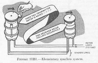
| 10B1. Introduction The most important unit in a modern transmission system is the synchro. Synchros of different types transmit, receive, or combine signals among stations which may be widely separated; for example, they transmit gun order signals from a computer to the automatic control equipment at a gun mount. The simplest types of synchro units are the synchro transmitter (sometimes called synchro generator) and the synchro receiver (sometimes called synchro motor). The transmitter is a device that transmits an electrical signal corresponding to the angle of rotation of its shaft. The receiver is a device that, when it receives such a signal, causes its own shaft (if not appreciably loaded) to rotate to an angle corresponding to the signal. Thus, as figure 10B1 shows, when the transmitter shaft is rotated, the receiver shaft rotates through exactly the same angle. |
 |
 |
 |
 |
 |
 |
 |
 |
| 10B2. How a synchro system works From the outside, a synchro transmitter or receiver looks much like an ordinary small motor or generator (fig. l0B1). So does the inside. See figure 10B2 (B). It has a bobbin-wound ball-bearing mounted rotor surrounded by a wound stator. The stator consists of three iron-core coils connected as in figure 10B2 (A), and terminating in three stator leads (S1, S2, S3). The two rotor leads (R1 and R2) shown in figure 10B2 (A) are connected to the rotor. See figure 10B2 (B). ‘The transmitter and receiver are identical in construction except that the motor has a damper (not illustrated) -a device that keeps it from “running away” when there are violent changes in its electrical input. |
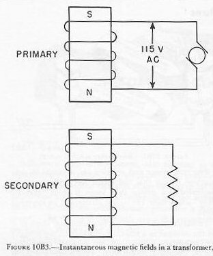
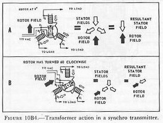
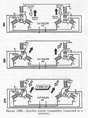
| To understand how a synchro functions, think of it for the moment as a transformer in which the primary and secondary are wound on separate cores (fig. 10B3). When a current flows in the primary, it forms a magnetic field in its core. As the current changes and reverses (which it does constantly, being an alternating current) so does the magnetic field. The changes in the field induce current in the secondary (whose circuit is closed through a load). The currents in the secondary produce their own magnetic field. At any instant, the induced or secondary field opposes in direction that produced by the primary. Figure 10B3 shows the field at a selected instant. At some other instant the fields might be of opposite polarity, but the primary and secondary fields are always opposed, whatever the instantaneous polarity. Now consider what happens in a synchro transmitter. Let 115-volt AC flow through the rotor. As shown in figure 10B4 (A), the rotor will produce a changing magnetic field. Its direction at some selected instant is shown by the black arrow. At that instant, the rotor field induces currents in the three stator fields, which are connected to a load. This transformer action produces in the three stator windings three fields (white arrows) which, when added to produce a resultant (symbolized by a large white arrow), exactly oppose the field in the (primary) rotor winding. If the rotor is now turned, say, 60 degrees clockwise, as in figure 10B4 (B), the rotor field, shown by the black arrow, will produce in the 3 stator coils 3 fields which will again add up to a resultant directly opposed to the rotor field. In each of the cases illustrated in figure 10B4, the rotor will induce in the stator coils currents corresponding to that position of the rotor, and to that one only. This is true for all positions of the rotor. Now consider a synchro transmitter connected to a receiver as in figure 10B5 (A), so that the rotors are fed by the same AC line and the stator coils of the receiver load the corresponding coils of the transmitter. The currents induced in the transmitter stator flow also in the receiver, and produce the resultant stator fields shown by the white arrows. Thus the receiver rotor, which produces a magnetic field similar to that of the transmitter rotor (because it is excited by the same AC line) always, because it is free to rotate, assumes exactly the same angular position (relative to the stator) as does the transmitter rotor. When the transmitter rotor is turned-say 30 degrees, as in figure 10B5 (B)-the resultant field produced by the stator turns too, as it did in figure 10B4; so does the receiver stator field. And the transmitter rotor, being free to follow, does. See figure 10B5 (C). NOTE: In this explanation, in the interest of simplicity, the effects of the voltages induced by the receiver rotor in its stator have not been explored. However, since the transmitter does not rotate except in response to whatever drives it, the net action is substantially as described above. |
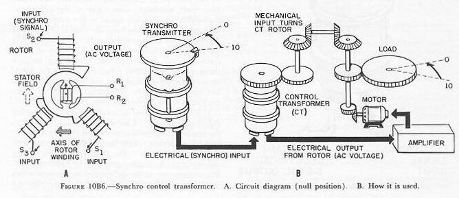
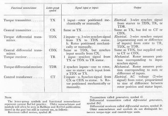
| 10B3. Other types of synchros The transmitter and receiver synchros described in the preceding section are only part of the synchro family. The other members are: 1. Synchro control transformer (CT). This device, like the synchro transmitter, has a wound rotor coil and three stator coils, but the internal construction is different. See figure 10B6 (A). The rotor is round instead of bobbin-shaped (to keep it from tending to line up with a magnetic field as a receiver rotor does) and is wound with finer wire to increase electrical impedance and limit the amount of current it will carry. The synchro control transformer has 2 inputs, 1 mechanical (its rotor is driven by the mechanism or load whose position it regulates) and the other electrical (the synchro signal from the transmitter which is to control the load). See figure 10B6 (B). The electrical (synchro) 3-wire input goes into the control transformer’s stator. The stator’s field acts as the primary of the transformer; the rotor is its secondary. The output thus comes from the rotor and varies with its position with respect to the stator. This output is not a synchro signal; it is a voltage whose value and polarity with respect to the AC supply depend on the position of the control transformer’s rotor with respect to the stator. This is how the rotor output varies with rotor position. Assume an unchanging field set up by the stator windings of a synchro control transformer, and let the rotor be turned through a full revolution. When the rotor winding is at right angles-dark arrow in figure 10B6 (A)-to the stator field-white arrow in figure 10B6 (A)-the induced voltage in the rotor will be at a minimum. This is called zero or null position. (Actually there will be small residual voltages, which can be neglected.) As the rotor turns, the output voltage increases and reaches a maximum when the rotor winding is parallel to the stator field. As the rotor continues to turn, the output falls. At 180 degrees the output is again zero, then increases and decreases as the rotor turns, much as in the first 180 degrees of revolution. But if in the first half revolution the instantaneous polarity of rotor output was in phase with that of the stator field currents, in the second it was opposed-180 degrees out of phase. |
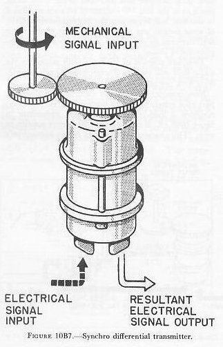
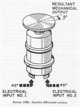
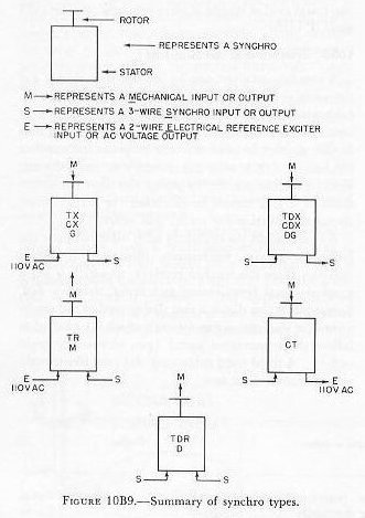
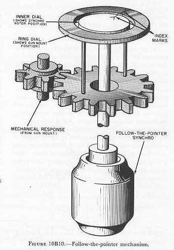
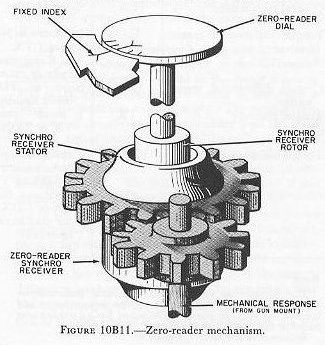
| Thus any position of the rotor with respect to the stator field will yield a characteristic output (considering both voltage and phase). Now consider the synchro control transformer as part of a system set up to control a power unit that positions a load. Suppose that the transmitter in figure 10B6 (B) is cranked from 10 degrees position to zero. This changes the direction of the transmitter’s stator field. Since the control transformer’s stator is connected to the transmitter’s stator, the control transformer’s stator field rotates similarly. This changes the value of the output of the control transformer’s rotor from zero. Since the control transformer’s output is too small to drive a motor, it is amplified. The amplifier’s output drives a motor which positions the load. But the control transformer’s shaft is so geared to the load that, as the motor drives the load, the control transformer’s input to the amplifier falls. When the control transformer’s output is zero again, the amplifier’s output has also fallen to zero, and the motor stops. At this point, the load is in the position required by the transmitter operator. The main advantage of a transmitter-control transformer system over a transmitter-receiver system is that friction and load weight are unimportant with a synchro control transformer, while they limit the accuracy of a synchro receiver. Any appreciable load increases a receiver’s angular error; sensitivity rather than load limits and a control transformer. The application of a synchro control transformer to a gun mount power drive is described in section 10D. 2. Synchro differential transmitter (sometimes called differential generator). The differential transmitter is a device which yields the sum or difference of two signals. The differential transmitter’s rotor and stator each have three windings. One input to the differential transmitter is a synchro signal to the stator winding. The other input is mechanical-that is, the rotor is driven mechanically to some angle. The output from the rotor of the differential transmitter is an electrical synchro signal that represents (depending on how the system is connected) either the sum or the difference of the mechanical and electrical signal inputs. See figure 10B7. The differential transmitter is not connected to the 115-volt AC line. 3. Synchro differential receiver (sometimes called differential motor). Like the differential transmitter, the synchro differential motor yields the sum or difference of two inputs. Both inputs (fig. 10B8) are electrical synchro signals. The receiver gives the sum or difference mechanically-generally by rotating a dial. The construction of the differential receiver resembles that of the differential transmitter, except that, like the synchro receiver taken up above, it is fitted with a damper. It does not have any direct connection to the 115-volt AC line. 10B4. Summary of synchro types The present functional classification of synchros, as described in OP 1303 (first revision in preparation at this writing), classifies all synchros into seven categories, each described by a group of letters. The classification recognizes not only the categories described in the 2 articles preceding, but also 2 broader categories-synchros designed primarily for systems producing an electrical control voltage signal, and synchros designed primarily for systems producing a mechanical movement (torque) or dial indication. As a convenience for the student in learning about the inputs, outputs, and functions of all the types of synchros, the table below and figure 10B9 show in summary form the types of synchros discussed above. For a fully detailed description of all standard Navy types of synchros, and for complete details of the nomenclature and symbol system that also shows the size and mark and mod of standard Navy synchros, see OP 1303 and OP 1755. 10B5. Synchro dial mechanisms A synchro receiver can be set up very simply (as shown in several figures earlier in this article) with a calibrated dial on its shaft to display information in terms of shaft rotation. It can also be set up so that it can display in addition the response of another mechanism (such as a gun mount) to the information. For example, such a set-up can show the movement of a gun mount in elevation (or train) in response to elevation (or train) gun order. A common set-up to display such information is the follow-the-pointer mechanism, illustrated in figure 10B10. Here the synchro receiver, to which is fed a synchro signal representing gun order, drives a dial. Surrounding this dial is a ring dial geared to the mechanism (in this case, a gun mount) which is supposed to follow the transmitted signal (gun elevator or train order). A third fixed calibrated dial (not illustrated) may surround these two. When a change in gun order occurs, the synchro rotor turns the dial. When the mount power drive or the gun pointer or trainer responds by moving the gun in accordance with the indicated order, this movement drives the response gearing, which turns the ring dial to follow the inner (synchro-driven) dial. When the two index marks match again, the gun mount is in gun order position. Synchros are often mounted, as in the above example, so that their stators remain fixed; however, they may also be bearing-mounted so that their stators can be mechanically rotated. A common example of such a mounting is the zero-reader mechanism. This mechanism is used to operate a dial which displays response of a gun mount or other load to a synchro signal. The example illustrated in figure 10B11 shows a synchro receiver to which is fed a synchro signal representing gun elevation (or train) order. This turns the rotor, which turns the zero-reader dial off the fixed index mark. As the gun mount is moved automatically (by the power drive) or manually (by the gun pointer or trainer), it drives the synchro stator through gearing so that the whole synchro (including the dial) rotates toward the fixed index mark. (The rotor and stator are electrically locked together by their magnetic fields.) The zero-reader dial shows the difference between the signal and the response. When the two are equal, their difference is zero, of course. When the indexes are matched, and the dial indicates “zero,” the gun mount position corresponds to gun order position. The process of matching the indexes is called matching zero readers. |
 |
 |
 |
 |
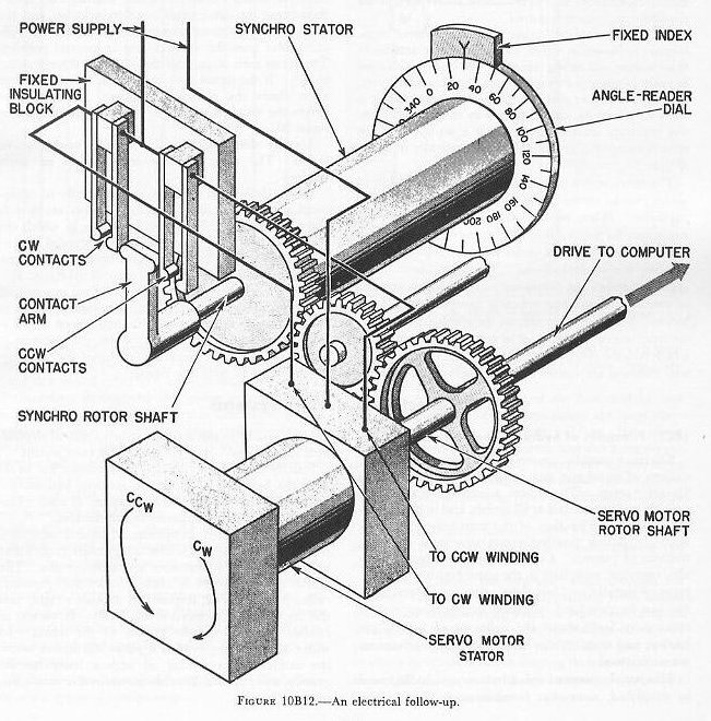 |
| When accurate values of quantities are required, synchros are used in pairs geared to each other so that one transmits coarse readings, the other fine readings. For example, one might be used to transmit 360 degrees per revolution, the other 10 degrees per revolution. This materially increases the sensitivity and accuracy of automatic transmission. In addition, it is evident that the graduations on the fine dial can be more easily read. These are called double-speed systems. It is possible to connect several synchro receivers to a single transmitter so that the transmitted quantity can be sent to several stations at the same time, and the values received will be synchronized at all stations. 10B6. Synchros and servos One of the limitations of synchros is their small output torque; hence, their use is limited to positioning dials and opening and closing contacts. But often the response to the indications must be made automatic. Mechanisms which provide automatic response are called follow-ups or servo mechanisms. An electrical follow-up employs an electric servo motor to provide the additional power required. One such follow-up, using a synchro control transformer, is shown in figure 10B6. As later articles in this chapter will show, this principle can be also used to position massive gun mounts and turrets. However, a synchro receiver can also be used for controlling a small motor in an instrument servo mechanism without requiring an amplifier. Such a set-up, in a fire control computer, is illustrated schematically in figure l0B12. The servo motor stator has two windings, either of which may be connected in series with a phase-shifting capacitor. When one winding is in series with the capacitor, the servo motor shaft turns clockwise; when the other winding is in series with the capacitor, the rotation is counterclockwise. The servo motor is energized through the follow-up control, which consists of two sets of sensitive contacts mounted on a fixed block. A light contact arm on the synchro rotor shaft operates one or the other set of contacts, depending on which way the synchro rotor turns. The counterclockwise contacts are connected to the servo motor winding which produces counterclockwise rotation (indicated by the arrows on the end of the motor), and the clockwise contacts are connected to the other winding. Assume that the remote synchro transmitter is sending a zero signal, and that zero bearing is set into the computer. The contact arms is in the neutral position; both sets of contacts are open; and the servo motor is motionless. As the director trains to 300, the transmitter sends a signal to the synchro receiver which rotates the contact arm clockwise far enough to close the counterclockwise contacts. This energizes the servo motor counterclockwise winding; the motor then turns the drive shaft counterclockwise, and the synchro stator rotates counterclockwise until the synchro rotor puts the contact arm in neutral position. The servo then stops, and the input to the computer is 30°. If the signal then changes to 20°, the contact arms closes the- clockwise contacts, and the servo drives the synchro stator 10° to make the remaining input 20°. Usually dials indicate the settings made by the servos. The dials may be zero readers or angle readers. Actual follow-up mechanisms, especially in equipment of recent design, have refinements omitted in this presentation. For example, servos in which the speed or power of response is proportional to the amount of error have many advantages, such as reducing oscillation or “hunting” around the signal. When coarse and fine synchros are used in a system, the servo mechanisms are often so constructed as to respond to a coarse error with high-speed response until it becomes a fine error, when the response is scaled down to the accuracy required for accurate synchronization with the signal. |