| GENE SLOVER'S US NAVY PAGES NAVAL ORDNANCE AND GUNNERY VOLUME 1, NAVAL ORDNANCE CHAPTER 11 ROCKETS AND GUIDED MISSILES |
| HOME INDEX Chapter 11 Rockets and Guided Missiles A. Rockets and the rocket principle B. Rockets fired from surface craft C. Aircraft rockets D. Guided missiles |
 |
 |
 |
 |
 |
 |
 |
 |
| B. Rockets Fired From Surface Craft 11B1. General As the previous article stated, the most important operational Navy rockets fired from surface craft are the spin-stabilized 5.0-inch (of which there is an entire family, with matching heads and motors), and two fin-stabilized A/S rockets, one 7.2-inch and one 12.75-inch. The 4.5-inch barrage rocket is now considered quite obsolete, and therefore is not taken up in this text. The 7.2-inch and 12.75-inch rockets are designed to serve primarily as launching devices for A/S charges (although the 7.2-inch type can be used against surface targets when equipped with the proper type of fuze). They arc therefore discussed elsewhere in this course, along with other A/S weapons. The remainder of this section is devoted to the 5.0-inch spin-stabilized surface-fired rocket. 11B2. 5.0-inch spin-stabilized rockets These rockets may be divided into three types, with respective maximum ranges of 2,500, 5,000, and 10,000 yards. All three have the same over-all length, so that they may be fired interchangeably from the same launchers. The shorter-range rockets, requiring smaller motors, are therefore provided with larger heads. For example, the 2,500-yard rocket has a small motor, and a large head that contains about 12 pounds of explosive. The 5,000-yard rocket is about half motor and half head; it carries a 9.6-pound bursting charge. The head of the 10,000-yard rocket contains only about 2.8 pounds of explosive. The bursting charges, heads, fuzes, and motor designations of 5.0-inch spin-stabilized rockets Marks 12, 10, 7, and 8 are compared in the table on page 250. |
| Rockets of this type are designed for shipboard use, to which end several launchers or launcher assemblies have been developed. Spin-stabilized rockets have proved very effective for beach neutralization and shore bombardment when fired by LSMR or other Inshore Fire Support type vessels. Their relative neutralization effect, as compared to 5”/38 AA Common projectiles, is as follows: 1 Mark 12 (at 2,500 yards) equals 2 AA Common projectiles; 1 Mark 10 (at 5,000 yards) equals 1.7 AA Common projectiles; I Mark 8 (at 10,000 yards) equals 1 AA Common projectile. Since an LSMR-IFS vessel has a firing rate of 250-350 rounds per minute, these rockets give these relatively small ships a fire power almost equal to that of a light cruiser in weight of projectiles per minute. The general-purpose and common rounds are particularly well adapted to PT-boat attacks at ranges up to 10,000 yards. |
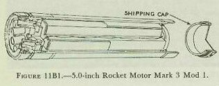
| 11B3. 5.0-inch rocket motor The 5.0-inch Rocket Motor Mark 3 is used to propel common and general-purpose 5.0-inch spin-stabilized rockets. It is shown in figure 11B1. The motor tube is about 22 inches long. It houses the propellant and serves as a combustion chamber. The motor tube has internal threads and an external bourrelet ring at each end. A shipping cap is screwed into the front end of the motor tube during shipment. The front closure is a sheet-metal disc pressed in position near the front end of the motor tube. This front closure seals the forward end of the motor tube and holds the igniter and propellant in place. There is a light, metal blow-out disc in the center of the front closure; on its inner surface a thin felt pad is cemented. Just inboard of this pad is the igniter, which is a flat, tinned case containing 35 grams of black powder and an electric squib. Two wires pass from the squib to the rear of the motor tube, where one wire is connected with the contact ring and the other wire is grounded to the motor tube at the nozzle-ring plate. A 1-inch thick felt washer is placed forward of the propellent grain to protect against accidental shock. The propellent used in this motor is an inhibited, cruciform extruded grain of Ballistite weighing about 10 pounds. A plastic inhibitor is cemented to both ends of the grain, and plastic inhibitor strips are cemented on the webs. These inhibitors control the burning area of the grain and thus regulate the pressure developed within the combustion chamber during the burning period. The nozzle-plate assembly consists of eight nozzles and a grid mounted on a nozzle plate. The nozzles have a 12-degree cant, which produces clockwise rotation when the rocket is fired. At the after end of the motor is an assembly consisting of a nozzle-plate ring and an insulated contact ring. The nozzle-plate ring has external threads which engage internal threads of the motor tube. The contact ring is riveted to the nozzle-plate ring, but electrically insulated from the latter. The nozzle-plate ring and the contact ring act as terminals of the igniter electrical circuit. A short-circuiting band creates a short circuit between the nozzle-plate ring and the contact ring; it is removed when the rocket is prepared for firing. The after end of the motor tube is sealed by a thin metal disc cemented in place within the rear of the nozzle-plate ring. Front and rear closures of the motor tube should remain in place at all times; if a closure has been broken, the motor should be turned over to an ammunition depot or disposed of by lowering into deep water. |
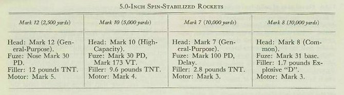
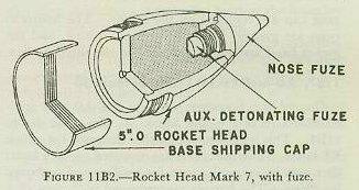
| 11B4. 5.0-inch spin-stabilized Rocket Head Mark 7 and fuzes Rocket Head Mark 7 and Mods is used for general-purpose rounds in the case of the 5.0-inch spin-stabilized rockets. This head, with nose fuze in place, is shown in figure 11B2. When shipped, the head is protected by a nose shipping plug and a base shipping cap. The head is closed at the after end, where it is threaded externally for assembly to the Motor Mark 3. The forward end of the rocket head is internally threaded to receive the adapter, on which the Auxiliary Detonating Fuze Mark 44 Mod 2 is mounted. When the adapter is screwed into the forward end of the body, the auxiliary fuze is properly positioned within the body. The Nose Fuze Mark 100 Mod 2 is then screwed into the adapter. The rocket head contains a 2.8-pound charge of TNT. The Nose Fuze Mark 100 is a selective-action type which is armed by rotation during flight. A selector in the side of the fuze body may be turned to DELAY or S. Q. (superquick). The amount of delay incorporated is 0.025 second. 11B5. 5.0-inch spin-stabilized Rocket Head Mark 8 and fuze The Rocket Head Mark 8 and Mods is also used for assembly with the Mark 3 motor. The Mark 8 head, designated for common rounds, is a hollow steel shell with a solid nose, containing a 1.7-pound charge of Explosive D. It is shown in figure 11B3. Its after end bears external threads for assembly to the motor; it also is threaded internally to receive an adapter. The Base Fuze Mark 31 is screwed into this adapter. The head is shipped with the base fuze in place, and protected by a base shipping cap. The latter is removed when the head is assembled to the motor. Personnel must not attempt to remove the base fuze from the head at any time. This fuze is armed by rotation during flight, and functions upon impact. 11B6. Stowing and assembly of 5.0-inch spin-stabilized rockets The motors of 5.0-inch spin-stabilized rockets should be stowed in the shipping boxes or tanks in which issued, in smokeless-powder magazines where temperatures are maintained below 90 degree F. Prolonged stowage at or about 100 degree F. is considered to be hazardous. Where magazine stowage in shipping boxes is not practicable, the Bureau of Ordnance prescribes special stowage conditions. Motors should not be stowed in the same compartment with or near electronic apparatus or antenna leads. At the discretion of the Commanding Officer, ready-service rounds may be stowed with the rounds pointing outboard if practicable. Fuzing of general-purpose and high-capacity rounds should be delayed as much as is commensurate with the tactical situation. The rockets should be kept in the shade, and should not be fired if motors have been exposed for more than an hour to temperatures outside the safe temperature limits specified on the motor tubes. In assembling the rocket, the gasket and shipping cap are first removed from the motor tube. Forward and after closures of the motor tube must remain in position. The base shipping cap is now removed from the head. A Mark 8 head must be examined to assure that the base fuze is in place; if not, the rocket head must be disposed of. If such a rocket head were assembled to a motor, the main charge would detonate when the motor was fired. Strap wrenches and bench clamps are now used to engage the threads of the motor and head until the seating surfaces meet firmly. In the case of the Mark 7 rocket head, a further step is to remove the nose plug and make sure that the auxiliary detonating fuze is present and screwed in the nose fuze. In disassembling 5.0-inch spin-stabilized rockets which have Mark 7 heads, the nose fuze is first removed and replaced by the nose plug. It is necessary to be sure at this stage that the short-circuiting band remains on the motor, or has been replaced thereon. Strap wrenches and bench clamps are then employed to disengage the motor and rocket head. The base shipping, cap is replaced on the head, and the gasket and shipping cap are replaced on the motor. The bourrelet rings are greased lightly to prevent rusting, and the rocket head and motor replaced in the shipping box. |
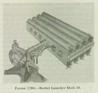
| In disassembling 5.0-inch spin-stabilized rockets which have Mark 7 heads, the nose fuze is first removed and replaced by the nose plug. It is necessary to be sure at this stage that the short-circuiting band remains on the motor, or has been replaced thereon. Strap wrenches and bench clamps are then employed to disengage the motor and rocket head. The base shipping, cap is replaced on the head, and the gasket and shipping cap are replaced on the motor. The bourrelet rings are greased lightly to prevent rusting, and the rocket head and motor replaced in the shipping box. 11B7. 5.0-inch Rocket Launcher Mark 50 One of the launchers used to fire 5.0-inch spin-stabilized rockets is the Mark 50, shown in figure 11B4. This is an 8-tube launcher designed for use on PT boats. Two launchers are mounted on each boat; they may be swung inboard for loading and outboard for firing. The barrels are arranged in 2 rows of 4 each, 1 row above and the other below a horizontal supporting shaft. Elevation is adjustable, and train is effected by turning the PT boat. When a firing button is depressed (on the bridge), one rocket is fired from each launcher. Current to fire a motor is fed to a rocket by means of the contact ring. The electrical impulse passes from the contact ring to the squib, causing the latter to set off the black powder in the igniter. |
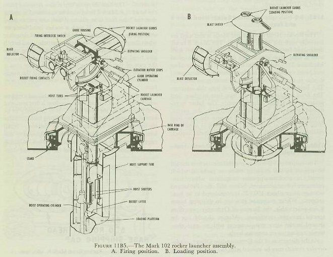
| 11B8. 5.0-inch Rocket Launcher Mark 102 Another launcher for 5.0-inch spin-stabilized rockets, the Mark 102, is designed for use on LSMR’s. This launcher is a mechanism for the automatic firing of rockets at a sustained rate of 30 rounds per minute. The assembly includes the deck-mounted rocket-launcher components, and a rocket-launcher ammunition hoist below decks, both of which are mounted on a carriage, power-driven in train. Elevation is accomplished by movement of the rocket-launcher guides. Remote control is possible in both elevation and train. The assembly is shown in figure 11B5. |
| The five principal components of the Mark 102 Mod 0 rocket-launcher are: a. The rocket-launcher guides, a pair of tubular guides mounted in a guide housing which is hydraulically moved from a vertical position for reloading. Mounted forward on the guides is a blast shield. b. The second component is the cradle, which supports the launcher guides. The cradle includes the elevating shoulder, a support for holding the launcher guides at the proper elevation for firing. c. The third component is the carriage assembly, which supports the cradle and the train and elevating power drives above decks. The carriage assembly also supports the hoist below decks. d. The fourth component is the stand, which is fixed to the deck and supports a roller path that provides for train of the rocket-launcher assembly. e. The final component is the hoist, which consists of 2 tubes and hydraulic lifting devices provided for simultaneous lifting of 2 rockets from a below-decks handling room into the rocket launcher guides. The hoist rotates in train with the rest of the rocket-launcher assembly. The carriage of this assembly represents an unusual adaptation of equipment designed for a very different purpose, in that it is really a modified 40-mm Carriage Mark 1 Mod 2. This carriage, described in chapter 9, has been modified by removal of the guns, firing mechanism, cooling system, loader’s platform, and other normal components. Various additions have been made, of which the principal items are the rocket-launcher cradle and ammunition hoist. Train and Elevation Power Drives Mark 4 Mod 3 are the same as those used with the 40-mm carriage, except that a train and elevation emergency start push button and a train emergency stop switch have been added. The stand is the 40-mm Stand Mark 1. Rocket-Launcher Assembly Mark 102 Mod 0 is subject to remote control by a director fire control system. A firing stop mechanism prevents firing into ship’s own structures. In automatic firing the loading of two rockets into the hoist tubes in the handling room below decks initiates the cycle of hoisting the rockets, transferring the rockets to the launcher guides, moving the guides to the firing position, firing the rockets, and returning the guides and hoist lifter to the loading position. Each step in this automatic cycle is controlled in proper phase by mechanically actuated switches. The intervalometer, a device in the firing circuit, introduces a 0.66-second delay between the firing of two rockets, to avoid blast interference. A safety interlock prevents the rocket-launcher guides from returning to reloading position until the rockets fired from both guides are clear. |
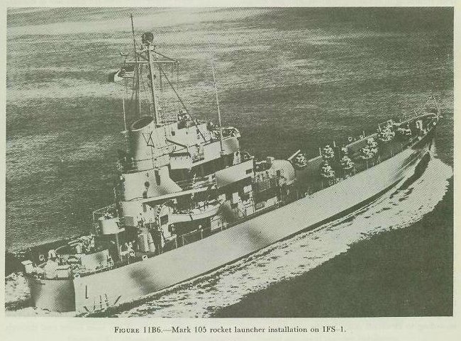
| 11B9. 5.0-inch Rocket Launcher Mark 105 The official nomenclature for this weapon is Rocket Launcher Assembly Mark 105 Mod 2, and it fires the 5.0-inch spin-stabilized rocket ammunition described in this section. It is a barrage weapon designed for installation aboard amphibious warfare support vessels such as inshore fire support ships (IFS). Figure 11B6 shows the U. S. S. Carronade, which is equipped with eight Mark 105 launchers. |
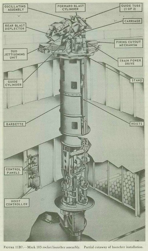
| Figure 11B7 is a view of the installed launcher assembly showing below-deck as well as above-deck components. The Mark 105 launcher resembles the Mark 102 in using twin rocket guide tubes and twin hoists, but it has several novel features and a higher rate of fire (48 rounds per minute). The main features of the Mark 105 rocket mount are summarized below: Structure. The launcher stand is a deck ring bolted to the rocket launcher foundation. The top face of the stand is the main support of the entire rocket launcher assembly. The carriage is a flanged base ring that trains on roller bearings and supports the oscillating assembly, the dud jettisoning unit, and all the other units that rotate in train. The oscillating assembly’s main components are the elevating shoulder and the guide tubes. The elevating shoulder is positioned according to elevation order by the elevating power drive. The guide tubes are moved in elevation by a hydraulic cylinder which positions them at either elevation order position (firing position) or at 90° elevation (loading position). This arrangement resembles that in the Mark 102 mount. The rocket guides are fitted with blast deflectors fore and aft. The rocket launcher ammunition hoist is suspended from the underside of the carriage base ring and rotates in train with it. The hoist extends downward inside a stationary barbette through the second deck to the third deck of the ship, which is the magazine level. Power drives. The electric-hydraulic train and elevation power drives used in the Mark 105 Mod 2 rocket launcher are similar to the Mark 10 drives used in Mark 3 Mod 4 40-mm (single) mounts. They are equipped with radial-piston A-ends and B-ends. The friction brakes and linkages in the original Mark 10’s have been omitted, there is no local (power) control, and the output speed ratio is modified. Normal launcher operation is director-controlled. Manual operation for maintenance and starting up the equipment is possible by declutching the power drive units and operating the handwheels by hand. The train power drive is on the right side of the carriage; the elevation drive is on the left. |
| Ammunition hoist. This is a manually loaded four-stage arrangement which lifts the ammunition rounds in pairs, one stage’ at a time, when the rocket guide tubes are in loading (vertical) position. The hoist is not of the endless-chain type. A fixed-tilt axial-piston pump feeds hydraulic fluid under pressure, through control valves, to a hydraulic cylinder. The piston rod of the cylinder is connected through wire rope tackle and pulleys to the four-stage lifter, which, upon each piston stroke (26.25 in.) moves upward or downward one stage (52.5 in.). The complete cycle of operation for a single-stage lift consists of a hydraulic piston downstroke (lifter upstroke), followed immediately by a piston upstroke (lifter downstroke). During the first lifter upstroke, pawls on the lowest part of the lifter engage the bases of the 2 rockets just loaded into the hoist, and raise them 1 stage. While the lifters downstroke, pawls in the hoist tube support the rounds in the tube. At the next lifter upstroke, the second-level lifter pawls engage the rounds, and carry them up the tube another stage, where they are held by stationary tube pawls during the next lifter downstroke. The process repeats as necessary to hoist the rockets into the rocket guide tubes. Electrical and mechanical interlocks start up the hoisting action when the hoist lower end is loaded, and prevent hoisting into the rocket guide tubes unless the tubes are in loading position. Rockets are loaded manually at the hoist lower end through shutters which align the rounds into proper position for loading. There is no provision for lowering ammunition through the hoist. The hoist hydraulic pump also supplies hydraulic fluid to the guide tube cylinder which shifts the guide between firing and loading position, and to the hydraulic cylinder in the jettisoning unit. A water line with quick-connect fittings provides for emergency flooding of the hoist. The hoist is also equipped with a central lubrication system. Dud jettisoning unit. This unit is a semiautomatic, electrically controlled, hydraulic-pneumatic operated device which provides for jettisoning misfired or otherwise defective ammunition that has been loaded from a remote point below decks. When jettisoning is required, the launcher is trained to relative bearing 90° or 270° (depending on which is the outboard direction), elevated to 5°, and the jettisoning unit is activated. A hydraulic cylinder in the jettisoning unit raises the unit’s cradle to 400; the rocket guide tubes are then elevated automatically to 40° to line them up with the jettisoning unit cradle. In the cradle, each aligned with one rocket guide tube, are two pneumatic cylinders. The piston rod of each cylinder terminates in a ram head. When the guide tubes are aligned with the jettisoning unit cradle, and the pneumatic pistons are in retracted position, each ram head is just behind the rocket in either guide tube. When the unit functions, each piston is pushed forward by air under 1,000 psi pressure from the ship’s supply, and the ram heads eject the rocket or rockets over the side into the water. (Jettisoning can, of course, be accomplished safely only when there are no ships or other obstructions close aboard. 11B10. Safety precautions in firing 5.0-inch spin-stabilized rockets General precautions pertaining to the firing of rockets, as partially outlined in article 11A7, are largely appropriate in the case of 5.0-inch spin-stabilized rockets as well. In addition, it may be reiterated that in the case of Mark 3 motors, front and rear closures of the motor tubes must remain intact at all times prior to firing. In Mark 8 common rocket heads, base fuzes must be in place before assembly. Note also that a 10-minute precautionary wait should be observed before unloading any misfired rounds. Mark 3 motors should not be allowed to stand on end for any considerable period of time (over an hour), and short-circuiting bands (on insulated contact rings) should be left in place until removed during the loading operation. Many special precautions must be observed in the operation of Mark 102 and Mark 105 launchers; these are detailed in appropriate ordnance pamphlets. |