| NAVAL ORDNANCE AND GUNNERY CHAPTER 12 TORPEDOES |
| C. Air System of a Mark 15 Torpedo 12C1. General The inside volume of the Mark 15 air flask is 23 cubic feet, and the flask is charged to a pressure of 2,800 psi. Obviously, a great deal of energy is stored in the air flask. Compressed air alone could be used to spin the turbines, and to drive the torpedo for a considerable distance. But both the speed and range of the torpedo are increased by passing the compressed air through a superheater before it reaches the turbines. The superheater increases both the volume and the speed of the gas that strikes the turbine blades. The main part of the superheater is a closed chamber-the combustion flask. A mixture of compressed air and alcohol is forced into the combustion flasks where it burns. The products of burning alcohol-carbon dioxide and steam-add to the volume of the exhaust gases. Because of the extreme heat generated in the combustion flash, water is sprayed in with the air and fuel to prevent damage to the super heater and turbines. In cooling the flask, the water is turned to steam and adds to the volume of gases that spin the turbines. Because compressed air and alcohol are the only sources of energy in the Mark 15 torpedo, compressed air is used for several things. Besides spinning the turbines, it also does the following: 1. At the end of an exercise run, it blows the liquid ballast out of the exercise head. 2. It forces fuel and water into the combustion flask. 3. It operates the igniter that starts the air-fuel mixture burning. 4. It operates the starting valve, which puts all the propelling and control mechanisms of the torpedo into operation. 5. It operates the gyro-spinning mechanism, which gives the gyro its initial spin and brings it up to full speed. 6. It keeps the gyro spinning during the whole torpedo run. 7. It supplies energy for the depth and steering engines, which operate the depth and steering rudders. |
 |
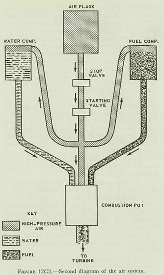
| 12C2. Functional description The air system of the Mark 15 torpedo is complex. It can best be explained by developing a diagram of it gradually, adding a few features at a time. Figure I2C1 shows the simplest possible type of air system. The supplies of air, fuel, and water must be kept in separate compartments. A pipe from each of these compartments goes to the combustion flask. The exhaust gases leave the flask and go to the turbines. The air system shown in figure l2C1 has several obvious defects. First, there is nothing to keep the air flask from exhausting into the combustion flask before the torpedo is fired. A starting valve must therefore be placed in the air pipe. This valve will open when the torpedo is fired, and release air from the flask into the rest of the air system. It is also desirable to have a stop valve in the main air line. This will make it possible to shut off the air flask from the rest of the torpedo during testing and repair. The stop valve is located between the air flask and the starting valve. In figure 12C1, fuel and water can reach the combustion flask only by gravity. An efficient system requires that fuel and water be forced out of their compartments by compressed air. But this should take place only after the starting valve has opened. The air lines that go to the fuel and water compartments will therefore join the main air pipe between the starting valve and the combustion flask. The air system has now been developed to the point shown in figure 12C2. |
 |
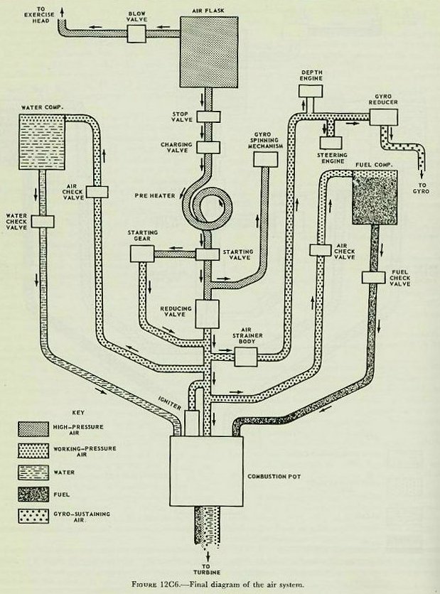
| But the system shown in figure 12C2 can easily be improved. First, a means for recharging the air flask is necessary. This calls for a charging valve, located between the stop valve and the starting valve. The air flask may now be recharged, as follows: 1. Close the stop valve (if it is open). 2. Connect the charging line to the charging valve. (Figure 12C3.) 3. Open the stop valve. 4. Open the valve in the flask to full pressure. (The starting valve is closed, and keeps air out of the rest of the system.) 5. Close the stop valve. 6. Close the valve in the charging line, and disconnect the line. The pressure in the air flask-2,800 psi-is much too high for most of the torpedo mechanisms. A reducing valve is therefore added, between the starting valve and the lines that go to the fuel and water compartments. The starting gear is connected to the starting valve by an air pipe. It allows the starting valve to open by venting the pressure in this pipe. When these features have been added, the air system has reached the stage shown in figure 12C4. A number of desirable features can still be added. For example, the starting gear begins to vent air from the starting valve as soon as the torpedo is fired. To prevent waste, this air should be carried back into the air system. Because there is a drop in pressure as the air passes through the starting gear, the pipe that returns the air from the starting gear will be connected to the low-pressure side of the reducing valve. Flask-pressure air is used to blow the exercise head at the end of an exercise run. We therefore need a pipe extending from the flask, which can be connected to the fitting in the exercise head bulkhead. A blow valve must be added in the pipe, so that it can be closed off at all times except when an exercise head is in place. In the system shown in figure 12C4, there is nothing to keep fuel and water from trickling and sloshing into the air system and combustion pot before the torpedo is fired. This can be prevented by putting check valves in both air lines, and in the fuel and water delivery pipes. The check valves are closed by low-pressure springs. As soon as the torpedo is fired, working-pressure air overcomes the spring pressure, and forces the check valves open. The air system has now been developed to the stage shown in figure 12C5. It is nearly complete. Only a few refinements are needed. As the air expands in the reducing valve, its temperature drops. But the reducing valve works more efficiently when it is warm than when it is cold. This difficulty can be overcome by preheating the air before it reaches the reducing valve. The preheater consists simply of one or more loops in the main air pipe, located between the charging valve and the starting valve. The preheater is mounted in the afterbody, where the hot exhaust gases from the turbine can flow over it. |
 |
 |
 |
 |
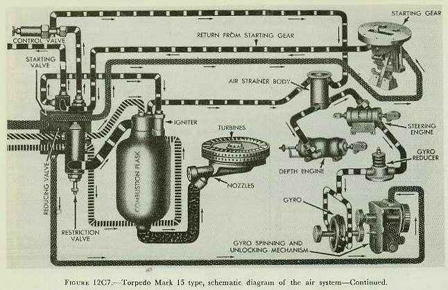
| High-pressure air is used to bring the gyro up to speed. The gyro-spinning mechanism is therefore connected to the main air pipe at a point between the starting valve and the reducing valve. The igniter, mounted in the combustion flask, is connected to the air system on the working-pressure side of the reducing valve. As soon as the torpedo is fired, working-pressure air will operate the igniter. Working-pressure air is also used to operate the control mechanisms. Because of the close tolerances in these mechanisms, the air is first passed through an air strainer body. From there, it goes to both the steering engine and the depth engine. Air from the strainer body is also used to sustain the speed of the gyro, after it has been brought up to speed by the gyro-spinning mechanism. But because the full working pressure is too high for this purpose, the air first passes through a gyro reducer, which decreases its pressure to about 125 psi. Figure 12C6 shows the diagram of the completed air system of a Mark 15-type torpedo. (Remember that this diagram is not intended to show the relative size or location of the parts. It merely shows how they are connected together.) Figure 12C7 is a schematic diagram that shows the actual appearance of the parts. The operation of the air system can be reviewed by showing what happens during a war shot. At the instant before firing, with torpedo loaded in the tube, the following conditions exist. The stop valve is open. The charging valve will let air flow to the starting gear; but its charging fitting is closed so that no air can leak outboard at that point. Because this is a war shot, the blow valve is closed. There is flask-pressure air in the preheater. There is flask pressure on the flask side of the starting valve and in the line from the starting valve to the starting gear. But the air is blocked off at the starting valve and starting gear, and there is no pressure in the system beyond those points. When the torpedo is fired the following things happen. (The operations are listed here in numbered steps. But remember that as soon as the starting valve opens, all the rest of the operations happen almost simultaneously.) 1. As the torpedo begins to move forward in the tube, the tripping latch in the tube strikes the torpedos starting lever, and throws it aft. 2. The starting gear vents the line from the starting valve, and the pressure in this line drops. 3. The starting valve opens. 4. Flask-pressure air goes to the gyro-spinning mechanism, which spins the gyro and quickly brings it up to full speed. The mechanism then shuts itself off, and uses no more air. 5. Flask-pressure air passes through the reducing valve, which drops it to working pressure-about 500 psi. 6. Air from the starting gear passes back into the system on the low-pressure side of the reducing valve. 7. Working-pressure air flows into the combustion flask through a restriction valve and an air whirl. 8. Working-pressure air opens the air check valve in the line to the fuel compartment. The pressure in the fuel compartment opens, the fuel check valve, and fuel flows into the combustion flask through a restriction valve and a fuel spray. 9. Working-pressure air flows to the igniter, and starts it burning. The igniter ignites the fuel-air mixture. 10. Working-pressure air opens the air check valve in the line to the water compartment. The pressure in the water compartment opens the water check valve, and water flows into the combustion flask through a restriction valve and a water spray. 11. A mixture of hot compressed air, combustion gases, and steam strikes the turbine blades, and spins the turbine. The turbine, through the gears and shafts of the main engine, spins the propellers. 12. Working-pressure air passes through the air strainer to the depth engine. The depth engine will then operate the depth rudders as soon as it gets an order from the depth mechanism. 13. Air from the air strainer body goes to the steering engine. The steering engine will then throw the steering rudders as soon as it gets an order from the steering mechanism. 14. Air from the air strainer body goes through the gyro reducer, which drops its pressure to 125 psi. This low-pressure air keeps the gyro spinning. |
 |
 |
| 12C3. Air-flask section The air-flask section includes the air flask and the fuel and water compartments; the midship section is permanently attached to its after end. The air-flask section is by far the longest section of an air-steam torpedo; in the Mark 15 type, it makes up more than half the total length. Figure 12C8 shows a sectional view of the air-flask section; the left-hand end of the picture is forward. Note that part of the flask has been cut out; it is relatively longer than it appears in the illustration. The air flask is made up of several forgings welded into a unit. It is closed at both ends by dome-shaped bulkheads, permanently welded in place. In the center of the forward bulkhead is a small, removable bulkhead, which gives access to the inside of the flask. A clamp and lock nut hold the small bulkhead in place, and the pressure inside the flask forces it firmly against its seat. A short length of pipe connects the removable bulkhead to the blow valve. As previously explained, the blow valve is opened for an exercise shot, and closed for a war shot. A nut and nipple connect the main air pipe to the after bulkhead of the air flask. The pigtail shape of this pipe allows the air flask bulkhead and the water compartment bulkhead to expand and contract when the temperature changes, without putting any strain on the nipples. The dry pipe goes straight into the flask from the main air pipe. At the end of an exercise run the torpedo floats almost vertically, with its tail down. The dry pipe keeps any water that may be in the flask from running down through the main air connection. The water compartment is enclosed by the outer shell of the torpedo. It is closed at its forward end by the after bulkhead of the air flask, and at its after end by the water compartment bulkhead. This bulkhead fits against a ground seat, and is held in place by screws. On its forward face, the water compartment bulkhead supports the doughnut-shaped fuel flask on four brackets. In the top of the fuel flask is a filling plug. When the torpedo is assembled, this plug lies directly under a second plug in the outer shell of the torpedo. This makes it possible to fill both the water compartment and the fuel flask through a single opening in the torpedo shell. In the rim of the water compartment bulkhead are four clamping nipples. To these are connected the two pipes that pressurize the fuel and water compartments, and the fuel and water delivery pipes. A safety feature-the blowout plug-is also mounted in the water -compartment bulkhead. If, through mechanical failure, flask-pressure air should enter the water compartment, a copper disc in the blowout plug would give way. The high pressure would then be vented through the plug and into the midship section, without serious damage to the water compartment or fuel flask. |
 |
 |
 |
 |
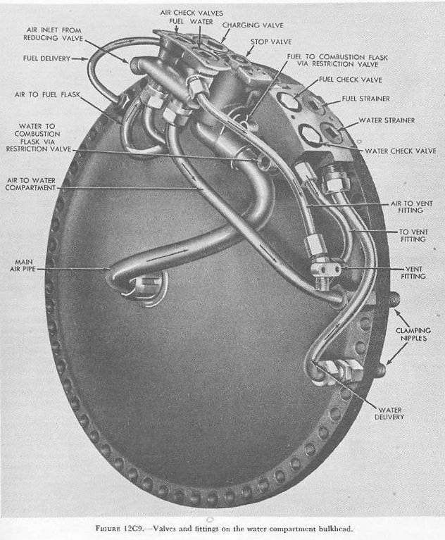
| 12C4. Fittings of the midship section The midship section is a short steel ring, riveted and soldered to the after end of the air flask section. Its after end is machined to form a joint with the after-body. At its forward end, the midship section is closed by the water compartment bulkhead. When the torpedo is assembled, the midship section is closed at its after end by the turbine bulkhead of the after-body. The midship section carries the stop and charging valves, the fuel and water check valves, the fuel and water strainers, the two air check valves, and the speed-setting socket. The combustion flask, igniter, reducing valve, and several other parts are mounted on the forward face of the turbine bulkhead, and are therefore considered parts of the afterbody. However, they arc enclosed by the midship section shell when the torpedo is assembled. Figure 12C9 shows the fittings attached to the after side of the water compartment bulkhead. All of these parts are enclosed by the midship section, and the valve housings are secured to the midship section shell by screws. Figure 12C10 shows the top of the midship section of an assembled Mark 15 torpedo. Note the openings in the shell. Fuel, air, and water pass between the air-flask section and the after-body through five separate lines. The connections for these lines can be secured only after the air-flask section has been assembled to the afterbody. The openings in the midship section make this possible. Two additional openings are not shown in figure 12C10. One of these provides access to a vent fitting, the other to the igniter. When the torpedo is under way, sea water floods the midship section through the openings in its shell. Some of the fittings in the midship section have to carry hot gases. The sea water that flows around them keeps them from overheating. 12C5. Stop and charging valves The stop and charging valves are contained in a single housing, as shown in figure 12C11. The opening at the right is connected to the air flask through the main air pipe; from the opening at the left, a pipe takes air to the starting valve. The stop valve plug makes an airtight connection against a washer on its seat. Inside the plug is the operating spindle. The small threaded follower screws into the inside of the plug. The shoulder on the operating spindle makes an airtight seal between the plug and the follower, so that no air can leak outboard through the stop valve. |
 |
 |
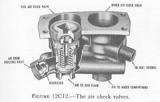
| To open the stop valve, the operating spindle is turned manually with a socket wrench. The spindle can not rise, because its shoulder is bearing against the plug. But the square shank at the bottom of the spindle turns the threaded stop valve carrier. The carrier rises, and lifts the stop valve off its seat. The stop valve must be opened to charge the air flask. It is closed again as soon as charging is completed. During final preparations for firing, the stop valve is opened shortly before the torpedo is loaded into the tube. The charging valve assembly consists of a plug valve and a spring-loaded check valve. The plug must be removed before charging the flask. Spring pressure on the check valve holds it shut, so that no air can leak outboard. When the charging fitting is screwed in, its tip unseats the check valve. 12C6. Check valves The 2 air check valves-1 for fuel and 1 for water- are identical, and are housed in a single casting. Figure 12C12 shows the air check valve housing, with the fuel air check valve partially cut away. Before the torpedo is fired, spring pressure holds both of the air check valves on their seats. The valves thus serve to isolate the fuel and water compartments from each other, and to keep fuel and water out of the air pipes. When the torpedo is fired, air from the reducing valve enters the housing through the nipple shown at the left in figure 12C12. It surrounds both valve stems, overcomes the spring pressure, opens the valves, and flows to the fuel and water compartments. The restrictor serves to smooth out any surges of pressure that might pressurize the fuel and water compartments unequally, with resulting damage to the fuel flask. The spaces above the valves are vented through a common opening. The venting feature prevents any air that may leak up past the valve stems from cushioning the action of the valves. The water air check valve will also serve as a safety device in the event that air leaks from the main air pipe into the water compartments before firing. If the pressure exceeds 5 psi, it will unseat the valve and exhaust into the combustion flask. The fuel and water check valves and strainers are mounted in a single housing, as shown in figure 12C13. The strainers remove any foreign matter that may be present in the fuel and water. The two check valves arc similar in principle to the air check valves. Before firing, spring pressure keeps the valves closed, and thus keeps fuel and water out of the combustion flask. On firing, pressure builds up in the fuel and water compartments, and unseats the valves. Fuel and water then flow through the strainers and check valves. The fuel and water check valves, like the air check valves, are vented through a common opening. The location of the four check valves in the midship section may be seen in figure 12C9. This figure also shows the location of the vent fitting. When the torpedo is assembled, a pipe carries any air vented through this fitting into the afterbody. 12C7. Restriction valves Before entering the combustion flask, both fuel and water flow through restriction valves, which control the speed of flow. Working-pressure air, before it enters the combustion flask, also flows through a restriction valve. The restriction causes a small decrease in air pressure; as a result, the pressure in the fuel and water compartments is higher than that in the combustion flask. It is this differential pressure- from 40 to 75 psi-that forces fuel and water into the flask. |
 |
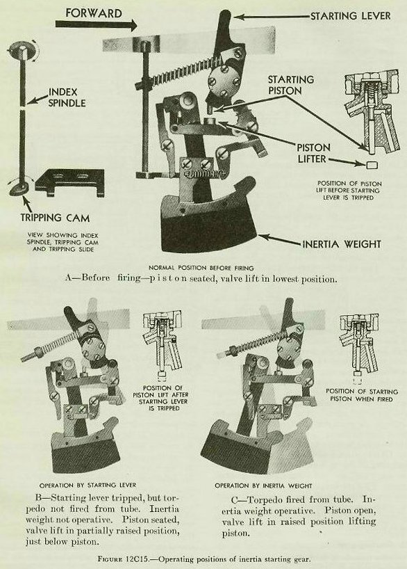
| 12C8. Starting valve The starting valve, reducing valve, and restriction valve are located in a single housing, as shown in figure 12C14. When the stop valve is closed, there is no pressure on either side of the starting valve. Its spring holds it shut. When the stop valve is opened, flask-pressure air flows in through the passage marked 1 in the illustration, and surrounds the bottom part of the valve. A deep groove runs around the bottom of the valve. Flask-pressure air fills this groove, pushing up against the top of it and down against the bottom. (NOTE: In this discussion, the terms up and down refer only to figure 12C14-not to the actual valve as assembled in the torpedo.) Because the area of the top of the groove is larger than that of the bottom, the total pressure on the top of the groove is greater, thus tending to overcome the spring pressure and open the valve. But, while the stop valve is being opened, air leaks up through a small passage in the starting valve and fills the space above it. This air goes through the connection at 2 (figure 12C14), to the starting piston of the starting gear. But, until the torpedo is fired, this passage is blocked off at the starting gear. By the time the stop valve is fully open, the space above the starting valve is filled with flask-pressure air. Since flask-pressure air is now pushing down on a much larger area than its pushing up on, air pressure helps the spring keep the starting valve closed. When the torpedo is fired, the starting gear vents the air line and the pressure above the starting valve drops. The pressure at the bottom of the valve forces it open, and flask-pressure air flows into chamber 3. From there it goes to three places. It goes to the right, and flows around the bottom end of the reducing valve stem. It goes through the control pipe (6), through a small restriction at 9, and into the control chamber (7). And it goes through outlet 4 to the gyro-spinning mechanism. 12C9. Reducing and control valves In figure 12C14, note the letters A, B, C, and D on the lower part of the reducing valve stem. These letters refer to the different cross-sectional areas that the air pressure acts on. In the picture, the valve is partly open. Imagine the valve stem in a higher position, with the valve completely closed. Flask-pressure air will then be pushing upward on the area A minus B, and downward on the area C minus B. Since A minus B is bigger than C minus B, the net force is upward, and the valve stays closed. But air is also going through the control pipe (6) and the restriction (9), into the control chamber (7). There it pushes down on area E, and forces the valve open. As soon as the valve is open, air flows into the reduced-pressure chamber (8). And there it pushes up against area D, and tends to close the valve again. So the valve stem moves up and down until it finds a point at which the upward forces exactly balance the downward forces. The control valve (figure 12C14) is a spring-regulated leak-off for the control chamber. As air pressure builds up in the control chamber, it moves the control valve against the pressure of its spring. Because the restriction at 9 is small, pressure builds up rather slowly in the control chamber. When it reaches a certain preset valve, the piston of the control valve uncovers a groove in the control valve housing, and some of the air leaks out. The control valve serves to keep the pressure in the control chamber constant. The actual pressure on the working-pressure side of the reducing valve depends on the pressure in the control chamber. Thus the working pressure can be adjusted, to some extent, by adjusting the pressure on the control valve spring. As the torpedo uses up the air in the air flask, the flask pressure gradually drops. But the working pressure remains constant. If the pressure in chamber 8 should start to drop, the upward pressure on area D would also drop. The valve would open wider, letting more air into 8. If the pressure in 8 should get too high, it would tend to close the valve and bring the working pressure back to normal. From the reduced-pressure chamber (8), the working-pressure air goes to three places. It goes through passage 11 to the igniter. It goes through 12 to the two air check valves. And it goes through the restriction in the restriction valve, into chamber 5, and from there to the combustion flask. The two upper passages in the restriction valve stem (figure 12C14) are for fuel and water. The three passages through the restriction valve stem control the rate at which fuel, air, and water enter the combustion flask. Thus the delivery rate, and therefore the running speed of the torpedo, can be changed by turning the restriction valve stem on its axis. Turning the valve stem will bring other passages, of different diameter, into position. 12C10. Starting gear When the torpedo is fired, the starting gear vents the pressure above the piston of the starting valve. The starting valve will then open, and release air to the reducing valve. Figure 12C15 represents the starting gear of a Mark 15 torpedo. Note that the right-hand side of the illustration is forward. The upper half of the illustration shows the condition of the starting gear before the torpedo is fired. The starting gear valve and piston may be seen in the small diagram at the upper right. The valve is seated, and spring pressure holds it in place. High-pressure air enters the valve housing through the opening at the left, which is connected by a pipe to the space above the starting valve piston. This high-pressure air pushes downward on the valve, and aids the spring pressure in keeping it shut. The starting gear operates when the torpedo is fired. The piston lifter then forces the piston upward, opening the valve. The high-pressure air above the valve is vented through the right-hand passage, permitting the starting valve to open. The starting gear of a Mark 15 torpedo is operated by two separate devices--the starting lever and the inertia weight. The starting gear is mounted in the top of the afterbody, with the starting lever projecting upward through an opening in the afterbody shell. When the torpedo begins to move forward in the tube on launching, a tripping latch in the tube engages the starting lever and throws it aft. The starting lever, through a mechanical linkage, moves the piston lifter upward toward the starting piston, but it does not lift the piston. As the torpedo gains momentum in the tube, the inertia weight trends to lag aft. The weight, through a second linkage, completes the upward movement of the piston lifter, and opens the valve. A spring-loaded latch holds the starting gear in this position, so that its valve can not close again during the torpedo run. Throughout the run, a small flow of air continues to pass through the starting gear, and is returned to the low-pressure side of the air system. As shown in the lower half of figure 12C15, neither the starting lever nor the inertia weight can operate the starting gear alone. Both must act together before the valve can open. This safety feature prevents the possibility of accidentally starting the torpedo before it is fired. The index spindle is operated manually with a socket wrench. Turning the spindle releases the latch, and permits the starting lever and inertia weight to return to their original positions. The index spindle is used to stop the torpedo after a test run on deck, and to reseat the starting piston before the air flask is charged. |
 |