| NAVAL ORDNANCE AND GUNNERY VOLUME 2, FIRE CONTROL CHAPTER 19 SURFACE FIRE CONTROL PROBLEM |
| HOME INDEX Chapter 19 SURFACE FIRE CONTROL PROBLEM A. General B. Analytical solution C. Graphic rangekeeping D. Mechanical solution-general E. Basic mechanisms F. Mechanical solution-basic rangekeepers G. Mechanical solution-establishing the horizontal plane |
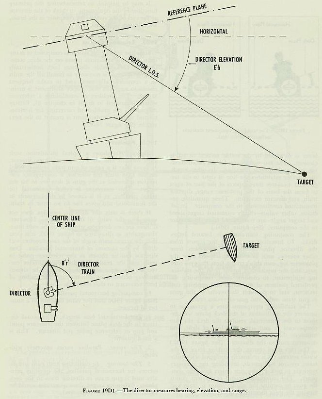
| D. Mechanical Solution-General 19D1. System elements The principal components of a fire control system are the gun director, the computer (or rangekeeper), the stable element (or stable vertical) and the gun mount, with essential transmission and communications equipment. All these components are aligned upon installation, with the fundamental reference planes of the ship, and are maintained in proper alignment by frequent checks. The gun director is located high in the shipís structure, to get away from smoke and other interference and to provide as distant a horizon as practicable. The director may be rotated to any desired point in bearing, and the optical sights and radar antenna contained in it can be elevated within desired limits. By means of optical equipment and radar, the director is able to measure (1) the range to the target, (2) the relative bearing of the target, as an angle in the deck plane, measured clockwise from the bow, to the perpendicular plane through the line of sight, and (3) the elevation of the target as an angle above the deck plane. Ordinarily, the latter is measured by the stable vertical or stable element. The last two quantities are called director train and director elevation. In other words, the director establishes the line of sight to the target, and measures three aspects of the line of sight to form the basis of the problem: range, director train, and director elevation. These quantities are transmitted continuously to the computer. In addition, other values-chiefly estimated target speed and target angle-are transmitted from the director to the computer. (See figure 19D1.) |
 |
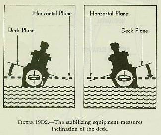
| The computing instrument is located below decks. Its functions are to take the inputs from the director, plus additional information from other sources, such as own shipís speed from the pitometer log, own shipís course from the gyro compass, and the mechanical inputs from the stabilizing equipment; to combine these, computing the predicted position of the target and applying corrections; and to transmit the results to the guns as gun train order and gun elevation order. The stabilizing equipment uses a gyroscope to measure the inclination of the deck plane with respect to the horizontal, resolves the deck tilt into components in and across the line of sight, and transmits this information to the computing instrument and to the director. (See figure 19D2.) The gun is, of course, the striking force of the whole system. It is ordinarily equipped with automatic control equipment, including the necessary receivers to pick up the gun orders from the computer. The automatic control equipment points the guns by turning the whole mount in train and moving the guns themselves in elevation. It may be helpful, in remembering the primary functions of the equipment, to think of the director as the eyes of the system, the computer as the brain, and the gun as the fist. |
 |
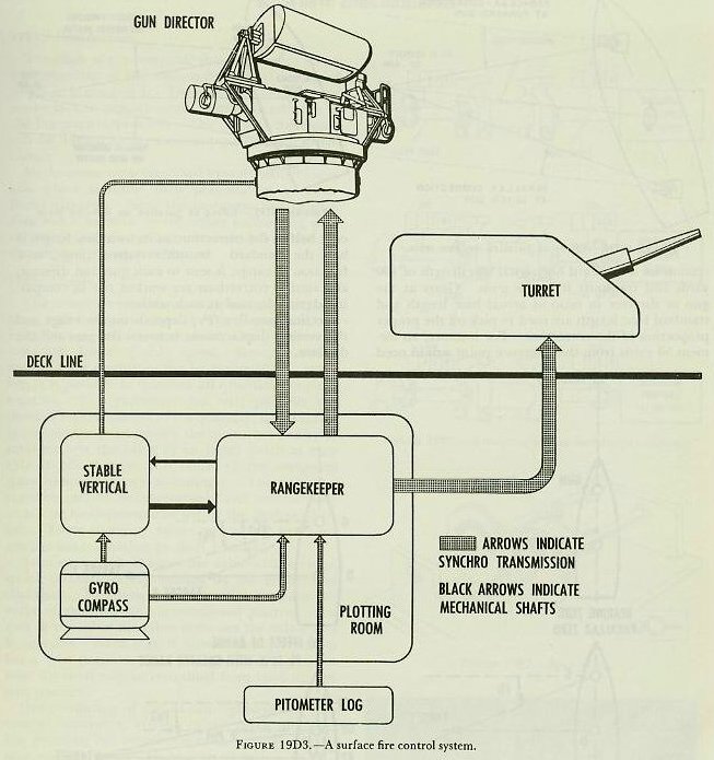 |
| 19D2. Reference systems Since the fire control system is composed of many units installed at various places on the ship, sometimes at considerable distances both horizontally and vertically, it is necessary to install all the units in a consistent alignment and to make frequent checks to ascertain that proper alignment is maintained. The problem of establishing a reference system is covered in detail in chapter 21, Battery Alignment; the problem of correcting for horizontal and vertical displacement is treated in the next article. (See figure 19D3.) |
 |
 |
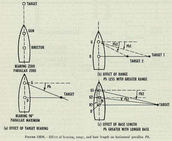 |
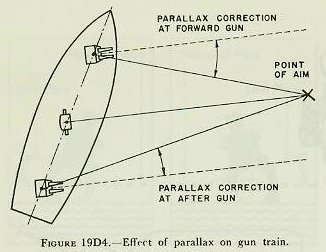
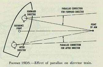
| 19D3. Parallax Figure 19D4 shows a typical installation with guns forward and aft and an amidships director. It shows that if a value of gun train order is based on the LOS from the director, a convergence correction is needed at the guns if they are to hit the target. This correction is called horizontal (or train) parallax, as it is caused by displacement in the horizontal and gives rise to an error in train. If there is only one director, parallax does not enter into the value of director train. However, if there are two directors which are to be used interchangeably, as illustrated in figure 19D5, it is clear that the actual train angle of the two directors will differ by the amount of horizontal parallax. One director can be chosen as the reference point in train and the reading of the other director corrected to it, or a reference point can be chosen midway between the directors and the reading of both corrected to that reference. In computing horizontal parallax, it can be seen from figure 19D6 that the value depends on a number of factors: 1. The horizontal base length. The actual distance in the deck plane between the reference point and gun or reference point and director. This is a fixed quantity. 2. The range. Parallax varies inversely with range. 3. The bearing. In correcting both guns and directors for horizontal parallax, the quantity actually used is gun train or director train in the deck plane. When on target, these quantities would be equal to Bígr and Bírí respectively. |
 |
 |
| Mechanically, the quantity is multiplied by the reciprocal of range, which can easily be done, rather than divided by range, which is more difficult. In some systems the computer works out the correction for a standard horizontal base length of 100 yards and transmits it to the guns. Gears at the gun or director in ratio of actual base length and standard base length are used to pick off the proper proportion of the correction. For instance, an element 50 yards from the reference point would need only half of the correction, as its own base length is half the standard. In other systems range, or a function of range, is sent to each gun and director, and similar corrections are worked out in computing devices located at each station. Vertical parallax (Pv) depends on the range and the vertical displacement between the gun and the director. |