G. Main-Battery Radar
20G1. General
Two radars are used with present-day main-battery fire control installations. These are Radar Equipment Mark 13 Mod 0 and Radar Equipment Mark 8 Mod 3. Although the Mark 13 has almost completely replaced the Mark 8 Mod 3 in the Fleet, the Mark 8 Mod 3 may still be found on some ships. Therefore a short description of this radar is given later.
In studying this section the student may find reference to chapter 16 helpful.
20G2. Cruiser radar installation
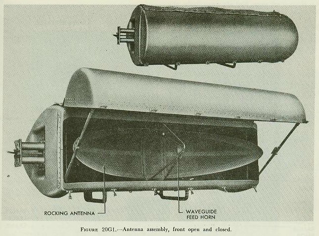
The majority of cruisers now in commission have two Mark 13 radars installed, one for use with each of the two Mark 34 directors. The antenna, which scans by rocking back and forth horizontally, is mounted on top of the director (fig. 20G1), and the radar transmitter-receiver is located inside the director.
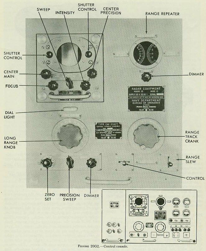
The main radar control unit for the forward Mark 13 radar is located in the main-battery plotting room near the Mark 8 rangekeeper. This unit, known as the control console
(fig. 20G2), is controlled by the radar operator.
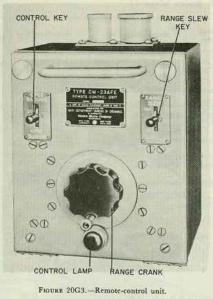
The control console for the after radar is located in the after main-battery control station topside, adjacent to the Mark 3 auxiliary computer. The radars are normally operated from the control consoles. However, provision is made for shifting control of either radar from the console to a remote-control unit
(fig. 20G3) at the control officer’s station in the associated director.
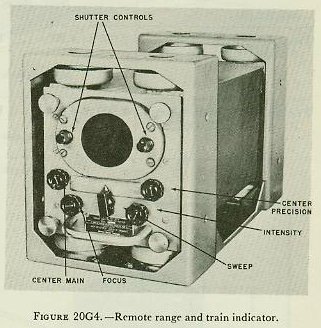
Two remote range and train indicators
(fig. 20G4) are located in each director, one to aid the trainer in getting on target by radar, and one to provide the control officer with continuous target data and to enable him to spot fall of shot.
In addition, two remote range and train indicators, one for each radar, are installed adjacent to each main-battery rangekeeping instrument-the Mark 8 rangekeeper in the plotting room, the Mark 3 computer in the forward topside control station, and the Mark 3 computer in the after topside control station. These remote indicators give the same B-scope presentations seen on the control consoles, and associated range counters give direct range readings for use of the rangekeeper or computer operator. Fall of shot may also be spotted from remote indicators.
Other components of the radars are below decks.
20G3. Beam characteristics
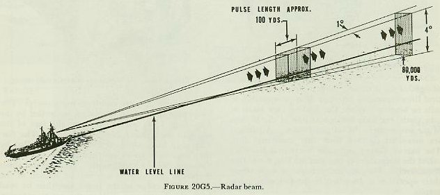
Figure 20G5 illustrates the radar beam of the Mark 13 radar. This beam consists of a series of pulses emitted at the rate of 1,800 per second, each pulse lasting 0.3 microsecond. Since radio energy travels at a constant speed of 328 yards per microsecond, the pulses theoretically are about 100 yards long or are represented by a 50-yard range interval on the scope, since scope presentations are for round trips of the pulses. The time interval between emission of pulses is 555 microseconds. Since the time required for a pulse to travel out 80,000 yards and return is 488 microseconds, there is ample time for each pulse to travel the maximum range and return before the next pulse starts.
In Radar Equipment Mark 13 Mod 0 the beam is 0.9° wide and 3.6° high. Actually, the radar beam is not as sharply defined as appears in
figure 20G5. It is strongest at points along its axis, becoming weaker as the angular distance from the axis increases.
20G4. Scanning
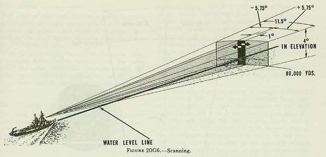
In scanning (
fig. 20G6), the rocking antenna mounted on top of the director causes the narrow beam to progress back and forth through a horizontal arc of 11.5° (200 mils) five times in each direction per second. The center of the scanning arc is rigidly aligned with the director line of sight, so that when the director is trained on a target, accurate bearing indication is given by the radar. With respect to the bearing of the director, the radar beam scans an area between + 5.75 and - 5.75 degrees.
NOTE. Positive (+) signifies increasing bearing, and negative (-) signifies decreasing bearing.
20G5. Scope presentation
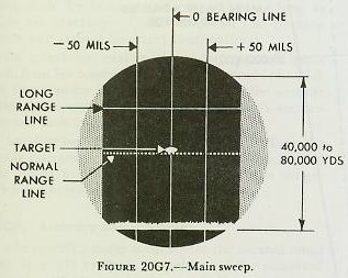
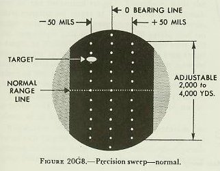
The scope presentations seen on the control console and on the remote range and train indicators are identical, and are B-type presentations. In this type of presentation, own ship is at the bottom of the scope, and the picture seen is that of a narrow, wedge-shaped segment of the earth. Figures 20G7 and 20G8 show the appearance of the scopes, both on the control console and on the range and train indicators, when set to MAIN SWEEP and when set to PRECISION SWEEP-NORMAL. Whenever the radar equipment views a target, a bright spot (the echo from the target) appears on the scope. The centerline or zero bearing line is aligned with the line of sight of the director. The distance between vertical lines represents intervals of approximately 50 mils in bearing. When the field of view starts at zero yards, the wide horizontal line at the bottom of the scope marks the outgoing pulse. All ranges are measured upward from this horizontal line. The narrow dotted and solid horizontal lines are called the normal-range line and the long-range line respectively. They are independent of each other; their operation is described in the following paragraphs.
20G6. Types of sweep
There are available in the Mark 13 radar three types of sweep: main sweep, precision sweep-normal, and precision sweep-long-range.
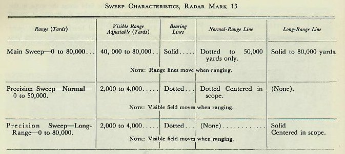
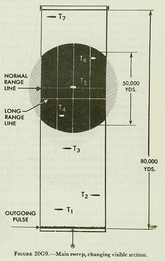
Main sweep. On main sweep the operator can view out to 80,000 yards. The total range appearing on the scope (
fig. 20G9) may be varied from 40,000 yards to the entire 80,000 yards. It is recommended that the field of view be set to 50,000 yards (
fig. 20G10). The operator can then view any 50,000-yard section of this 80,000 yards by adjusting the center main control (see
fig. 20G2) on the console, which moves the field across the scope in the same manner that a window shade may be moved behind an opening (
fig. 20G9).
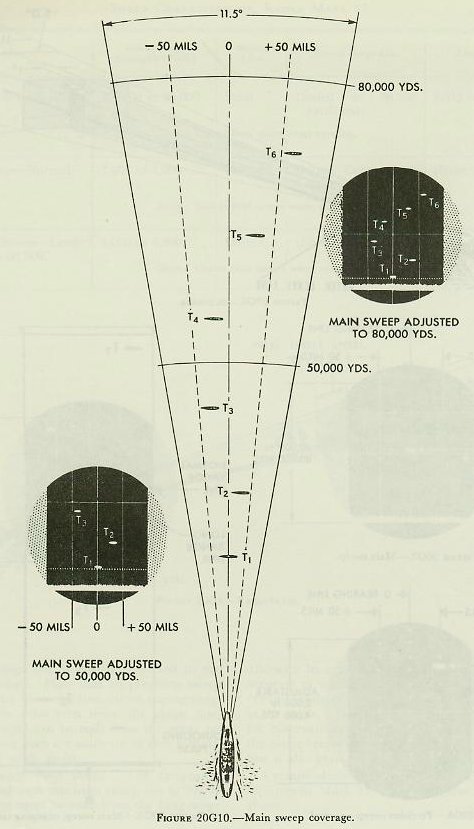
There are three solid bearing lines, the outer lines each 50 mils out from the center bearing line. The total width of the scope is approximately 200 mils, 100 mils either side of the center bearing line.
Two range lines are visible on main sweep. The long-range line, which is solid, is controlled by the long-range knob, and moves over the face of the scope to the maximum of 80,000 yards. The normal-range line, which is dotted, is controlled by the range-track crank and moves over the face of the scope only to 50,000 yards. The operator shifts the range line until it touches the bottom of the echo. The range to the target can then be read from the long-range dial or the range repeater.
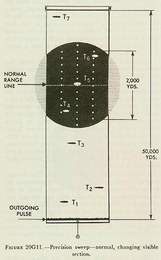
Precision sweep-normal. On precision sweep the operator can view to a maximum of 50,000 yards, but only 2,000 to 4,000 yards of this at a time. The desired visible field on precision sweep, which may be any value between 2,000 and 4,000 yards, is set by an internal adjustment and usually is not changed by the operator. In this discussion it is assumed that the selected field visible on the scope is 2,000 yards (
fig. 20G11). The operator can select any 2,000- to 4,000-yard section out of the normal 50,000 yards available. This is done by operating the range-track crank, which moves the visible field in the scope in the manner of a roller shade. The range line is dotted and fixed in the center of the scope. Note that on precision sweep the field, and not the range line, moves during ranging. When the echo rests upon the range line, range to the target can be read from the range repeaters. Bearing lines are made up of dots indicating spaces 200 yards apart.
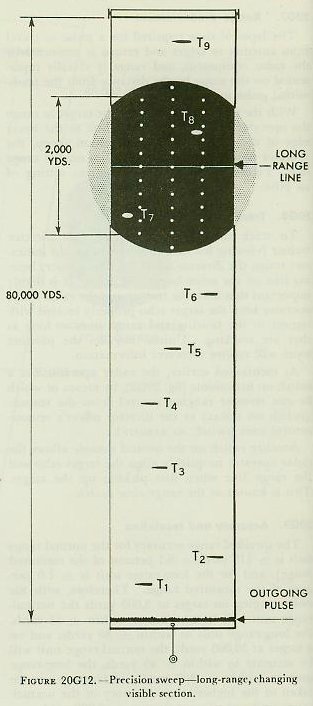
Precision sweep-long range. The long-range unit can be used with precision sweep out to 80,000 yards, but range must be read from the long-range dial with its coarse graduations, and will not be as accurate as with the normal-range unit, the range reading dials of which have graduations as small as 10 yards. Precision sweep-long-range is used for observation only; range is not transmitted to the range-keeper. In this case the solid long-range line is also fixed in the center of the scope.
A recapitulation of sweep characteristics of Radar Equipment Mark 13 Mod 0 is given in the table above.
20G7. Range measurement
The lapse of time required for a pulse to travel from antenna to target and return is measured by the radar equipment, and range is visually represented on the scope by the distance from the transmitted pulse to an echo.
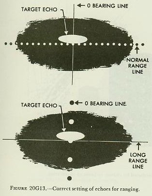
With the main sweep, to track the target in range the operator brings either range line to the lower edge of the echo. With the precision sweep, the operator moves the echo until it lies on the range line.
Figure 20G13 shows the correct setting of an echo.
20G8. Tracking in bearing
To track the target in bearing, the director trainer (viewing his remote range and train indicator) trains the director until the zero (center) bearing line on the scope bisects the echo. It is highly important that both the trainer and the radar-range operator keep the target echo properly located with respect to the bearing and range lines as long as they are tracking. Unless they do, the plotting room will receive incorrect information.
As mentioned earlier, the radar operator has a switch on his console (
fig. 20G2), by means of which he can transfer ranging control from the console (switch on LOCAL) to the director officer’s remote-control unit (switch on REMOTE).
Another switch on the control console allows the radar operator to quickly align the target echo and the range line when first picking up the target. This is known as the range slew switch.
20G9. Accuracy and resolution
The specified range accuracy for the normal range unit is ± [15 yards + 0.1 percent of the measured range], and for the long-range unit is ± 1.0 percent of the measured range. Therefore, with the units ranging on target at 3,000 yards the normal-range unit will be accurate to within ± 18 yards, the long-range unit to within ± 30 yards; and on a target at 30,000 yards, the normal-range unit will be accurate to within ± 45 yards, the long-range unit to within ± 300 yards. Advantage can be taken of the higher range accuracy of the normal-range unit out to a maximum of 50,000 yards.
Target bearing accuracy is ± 0.1 degrees (2 mils), or better. If exact alignment were possible, an accuracy of ± 1 mil might be attained.
Resolution-that is, the minimum separation between two targets in order that accurate range and bearing of either target may be obtained-depends upon beam width and pulse length. The narrow beam (1 degree) and short pulse (0.3 microseconds) of the Radar Equipment Mark 13 Mod 0 give excellent resolution in both bearing and range, particularly on precision sweep.
The length in range of the target echo gives an indication of the minimum separation between two targets on the same bearing which will permit complete resolution of those targets in range.
This echo length on Radar Equipment Mark 13 Mod 0 is about 100 yards for a target of negligible range depth.
If two targets are separated in range by slightly more than 100 yards, energy reflected from the second target will reach the position of the first target on its way back to the antenna just after the last reflected energy has left the first target, and a separate echo will appear for each target. But if the two targets are separated in range by less than 100 yards, the first reflected energy from the second target will reach the of the first target while energy is still being reflected from it, and a single large echo will appear.
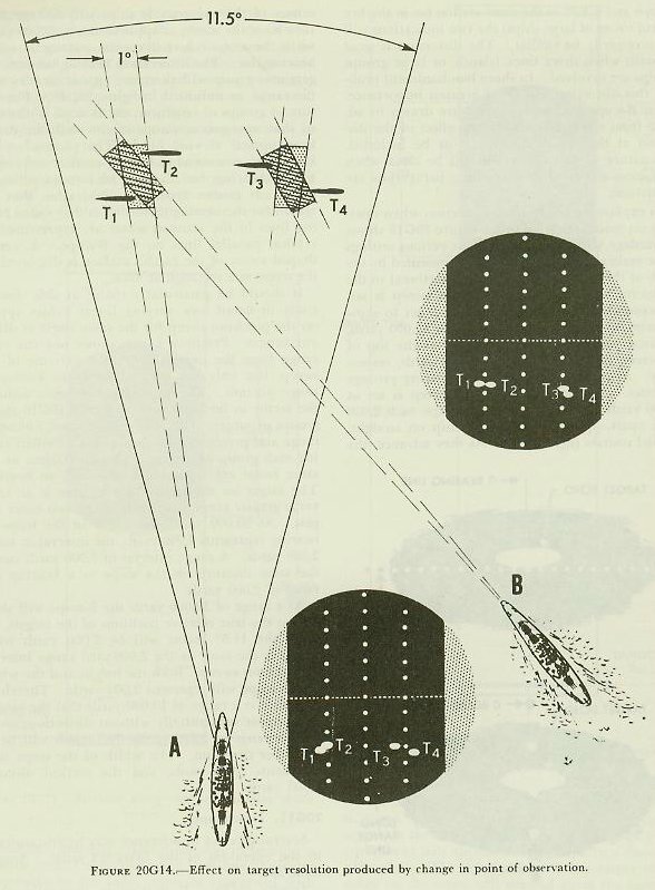
Resolution of two targets at the same range but different bearings depends upon the beam width. The beam width is approximately 1 degree. Therefore, if two targets are separated by more than 1°, the beam leaves the first target before it strikes the second, and two echoes will appear upon the scope. If the separation of two targets is less than the beam width of 1°, a single wide echo (generally asymmetrical) will appear. Referring to
figure 20G14, targets 1 and 2 as seen from position B and targets 3 and 4 as seen from position A are sufficiently separated to give good bearing resolution, whereas targets 3 and 4 as seen from position B and targets 1 and 2 as seen from position A are too close together in bearing.
It should be apparent to the student that the separation in yards necessary for bearing resolution between two targets varies with range; thus, as the targets become closer to own ship, one merged target pip may separate into two single pips. Also, an experienced operator can often improve the bearing resolution by judicious use of the RECEIVER GAIN control. By reducing the gain, two signals which merge may be wholly or partially separated.
20G10. Distortion
Since a B-scope does not show the true plan-view relationship of targets but shows a pie-shaped segment of the earth’s surface as a rectangle, the result is a picture somewhat distorted in range and bearing. As will be explained, distortion in bearing is not the same as distortion in range. In order to interpret B-scope presentations properly, the operator must be familiar with the effects of distortion; at the same time, however, it is important to remember that neither kind of distortion in any way affects the accuracy of range and bearing to a target whose echo is properly set on the range lines and bisected by the zero bearing line.
Range distortion. Range distortion is present in Radar Equipment Mark 13 Mod 0, since arcs of circles drawn from own ship as center appear on the scope as straight lines. However, because of the small angle (11.5°) through which the beam scans, range distortion is insignificant except at long ranges, and may be ignored.
Bearing distortion. The distortion in bearing is of much greater magnitude and therefore of greater importance to the radar operator concerned with the method of presenting the scanned surface area on the B-scope. Bearing distortion should be understood by all officers and operators, because all targets in the scanned sector within the range of the equipment will appear on the scope in a distorted plan view. The relationship of one target to another on the scope will depend upon the range of the targets. Where it is possible to see both the B-scope and a PPI at the same station (as in the fire control tower of large ships) the two indications will not necessarily be similar. The distortion is most apparent when shore lines, islands, or large groups of ships are involved. In shore bombardment problems this distortion will be of greatest importance. When B-scope charts of a target are drawn in advance from navigation charts, the effect of the distortion at the expected range must be included. The nature of this distortion will be clear when the factors discussed in succeeding paragraphs are understood.
An explanation of bearing distortion when operating on main sweep follows.
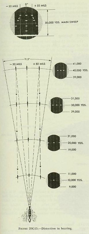
Figure 20G15 shows the yardage visible on the screen at various settings of the main sweep. The yardage represented by the width of the screen at the top is proportional to the maximum range to which the main sweep is set. For example, when the main sweep is set to show a maximum range of 40,000, 60,000 or 80,000 yards, the total yardage visible in bearing at the top of the screen is 8,000, 12,000, or 16,000 yards, respectively. As you progress down, the bearing yardage decreases. Assume that the main sweep is set at 50,000 yards and that three target ships, each 2,000 yards apart, approach the radar ship on straight, parallel courses (
fig. 20G15). As they advance, the echoes of the two outside ships will diverge until they leave the screen at approximately 20,000 yards, while the center echo will continue along the center bearing line. The intervals in bearing between targets in a group will therefore appear to vary with the range, as indicated in
figure 20G15. The picture of groups of targets on the B-scope is distorted so that wrong conclusions might easily be drawn from optical viewing only. The picture on the B-scope gives somewhat the appearance of perspective in bearing, but there is no foreshortening in range. It is seen from this illustration that the reason for the bearing distortion is that radial bearing lines in the scanned sector are represented by vertical parallel lines on the B-scope. A wedge-shaped sector of the earth’s surface is displayed on the scope as a rectangular area.
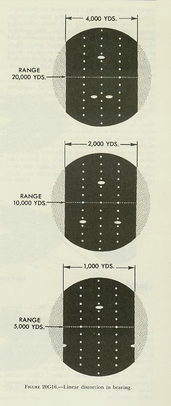
It should be particularly useful at this time to study in detail how varying linear values appear on the precision sweep for the same angle at different ranges. Precision sweep shows not the total range from the radar ship to the extreme of the sweep, but only the selected 2,000- to 4,000-yard range portion. The following discussion assumes the sector to be 2,000 yards.
Figure 20G16 shows groups of targets at 20,000-, 10,000-, and 5,000-yard range and precision sweep’s appearance when viewing each group of targets. The two targets at the same range are separated 1,000 yards in bearing. The target on the center bearing line is at 1,000 yards greater range than each of the two outer targets. At 20,000 yards the width of the scope in bearing represents 4,000 yards, the interval in range 2,000 yards. A range interval of 1,000 yards covers the same distance on the scope as a bearing distance of 2,000 yards.
At a range of 10,000 yards the B-scope will show almost the true relative positions of the targets, because the 11.5° sector will be 2,000 yards wide, which is the same as the 2,000-yard range interval of precision sweep. Both the height and the width of the scope will represent 2,000 yards. Therefore, it is only at a range of 10,000 yards that the targets will appear substantially without distortion.
At a range of 5,000 yards, distortions will be in the other direction. The width of the scope now represents 1,000 yards, and the vertical distance 2,000 yards.
20G11. Interference
Several types of interference may be encountered in the operation of the Mark 13 radar. Among these are:
Double echoes. It is possible, especially when ranging on strong echoes from nearby targets, that secondary (ghost) echoes may appear on the screen. This is due to the reflected energy from the target ship hitting the radar ship and being reflected a second time from the target ship. The operator should become familiar with this phenomenon by observing such targets on a practice run. These ghost echoes will always appear at twice the range of the original targets, and may be distinguished by observing the range of the echo and its appearance as compared to the original echo.
Shore interference. When observing shore lines, there will be a small area (generally of negligible importance with the excellent discrimination of the Mark 13 radar) in which targets may be obscured by land background.
Minor lobes and nearby objects. The power from the antenna radiated in the minor lobes is small compared with that in the major lobe. Nonetheless, minor lobes may cause echoes from a large target close to the equipment. In a horizontal line across the screen will be one bright echo and several dimmer ones. It is characteristic of minor-lobe echoes that they all will be at exactly the same range and will fluctuate together with the main echo.
A small target with poor reflecting surface at close range may also send back weak echoes. It is therefore possible that, if a strong echo and one or more weak echoes are observed at exactly the same range, it may be assumed that the minor lobes cause the weaker signal. Careful checks should be made to prevent misinterpretation of such an occurrence.
Interference from other radars. Other radars operating in the vicinity may produce a background noise on the scope which will not, in general, affect operation.
Sea return. At times, particularly in stormy weather, large, irregular, and fluctuating pips may appear on the screen. This is called sea return, and is caused by echoes from waves. Reducing the receiver gain will eliminate much of the sea return and tend to sharpen the outlines of the target echoes.
20G12. Spotting
The Mark 13 radar can be effectively used to spot fall of shot in both range and deflection. Shell splashes appear on the B-scope as fluctuating echoes which last for several seconds, depending upon the size of the projectile and the range. Salvos produce larger or multiple echoes on the scope.
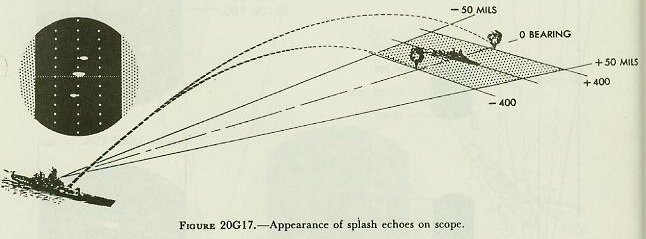
Radar spotting has proved to be both accurate and reliable to the full range of the guns and is, of course, independent of visibility conditions. In using the B-scope for spotting, precision sweep gives the best indications of shell splashes and is normally used.
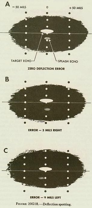
For best results, accurate tracking with the target echo kept adjacent to the range line and bisected by the center bearing line is essential. The error of the MPI from the target echo can then be easily estimated, using the dots on the bearing line, which are 200 yards apart, as a yardstick range. It is also helpful in deflection spotting to keep in mind that the average width of the splash echo may be taken as approximately 18 mils.
Figures 20G17 and
20G18 give examples of splash echoes as they would appear on the scope for various range and deflection errors.
20G13. Radar Equipment Mark 8 Mod 3
As stated earlier, the Mark 8 Mod 3 radar was the predecessor of the Mark 13 radar and may still be found in some ships. Since this radar is very similar to the Mark 13, both in construction and in operation, only the major differences are pointed out here:
1. Packaging of the equipment is not as compact nor as easily accessible for maintenance.
2. There is only one range line.
3. On main sweep, the operator can view to 60,000 yards, but can measure range only to 44,000 yards.
4. It has three sweeps instead of two: main sweep, 0 to 44,000 yards; expanded sweep, 0 to 20,000 yards; and precision sweep, any 2,000 yards out to 44,000 yards.
5. All bearing lines are solid.


 The control console for the after radar is located in the after main-battery control station topside, adjacent to the Mark 3 auxiliary computer. The radars are normally operated from the control consoles. However, provision is made for shifting control of either radar from the console to a remote-control unit (fig. 20G3) at the control officer’s station in the associated director.


 There are three solid bearing lines, the outer lines each 50 mils out from the center bearing line. The total width of the scope is approximately 200 mils, 100 mils either side of the center bearing line.
Two range lines are visible on main sweep. The long-range line, which is solid, is controlled by the long-range knob, and moves over the face of the scope to the maximum of 80,000 yards. The normal-range line, which is dotted, is controlled by the range-track crank and moves over the face of the scope only to 50,000 yards. The operator shifts the range line until it touches the bottom of the echo. The range to the target can then be read from the long-range dial or the range repeater.


 An explanation of bearing distortion when operating on main sweep follows. Figure 20G15 shows the yardage visible on the screen at various settings of the main sweep. The yardage represented by the width of the screen at the top is proportional to the maximum range to which the main sweep is set. For example, when the main sweep is set to show a maximum range of 40,000, 60,000 or 80,000 yards, the total yardage visible in bearing at the top of the screen is 8,000, 12,000, or 16,000 yards, respectively. As you progress down, the bearing yardage decreases. Assume that the main sweep is set at 50,000 yards and that three target ships, each 2,000 yards apart, approach the radar ship on straight, parallel courses (fig. 20G15). As they advance, the echoes of the two outside ships will diverge until they leave the screen at approximately 20,000 yards, while the center echo will continue along the center bearing line. The intervals in bearing between targets in a group will therefore appear to vary with the range, as indicated in figure 20G15. The picture of groups of targets on the B-scope is distorted so that wrong conclusions might easily be drawn from optical viewing only. The picture on the B-scope gives somewhat the appearance of perspective in bearing, but there is no foreshortening in range. It is seen from this illustration that the reason for the bearing distortion is that radial bearing lines in the scanned sector are represented by vertical parallel lines on the B-scope. A wedge-shaped sector of the earth’s surface is displayed on the scope as a rectangular area.
 It should be particularly useful at this time to study in detail how varying linear values appear on the precision sweep for the same angle at different ranges. Precision sweep shows not the total range from the radar ship to the extreme of the sweep, but only the selected 2,000- to 4,000-yard range portion. The following discussion assumes the sector to be 2,000 yards. Figure 20G16 shows groups of targets at 20,000-, 10,000-, and 5,000-yard range and precision sweep’s appearance when viewing each group of targets. The two targets at the same range are separated 1,000 yards in bearing. The target on the center bearing line is at 1,000 yards greater range than each of the two outer targets. At 20,000 yards the width of the scope in bearing represents 4,000 yards, the interval in range 2,000 yards. A range interval of 1,000 yards covers the same distance on the scope as a bearing distance of 2,000 yards.
