US NAVY
FIRE CONTROL PAGES
NAVAL ORDNANCE AND GUNNERY
VOLUME 2, FIRE CONTROL
CHAPTER 24
ANTIAIRCRAFT PROBLEM
ANALYTICAL
Chapter 24 Antiaircraft problem analytical
A. Target positioning
B. Ballistic computations
C. Gun positioning
24B1. Statement of the problem
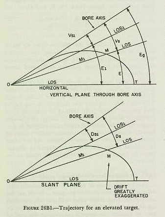
The LOS, as roughly established in article 24A5, must further be corrected for the effects of gravity, drift, wind, loss of initial velocity (I.V.), nonstandard atmospheric conditions, and certain geometric errors introduced by the fact that the motion of the gun is limited to train in the deck plane and to elevation in a plane perpendicular to the deck.
Corrections for these effects and for relative target motion are summed up to form the two lead angles, one in the vertical plane and one in the slant plane. These lead angles are called sight angle (Vs) and sight deflection (Ds), respectively. Although computed and applied separately, together they represent the total lead angle, that is, the angle the gun bore axis must be pointed ahead of the present LOS to obtain a hit on a moving target.
In the succeeding paragraphs it will be assumed that the trunnion axis is horizontal, and a closer examination will be made of the effects to be considered in determining the lead angles Vs and Ds. Consideration will be made for: (1) own-ship and target motion; (2) trajectory curvature caused by gravity and drift; and (3) effects of wind, I.V. variation, and air density variation.
24B2. Prediction of relative target motion and advance target position
During time of flight the target moves from the position it occupied at the instant of firing. The gun must be fired, not at present target position, but at the advance position the target will occupy at the end of Tf. The LOS is directed at the present position, so the gun must lead the LOS and the target, by corrections in elevation and deflection.
Relative target motion has been described by the linear rates dR, RdE, and RdBs. Predictions for relative target motion, then, may be expressed by the equations:
Rt (the predicted change of range during Tf) =dRXTfXK
Vt (the predicted angular change in minutes of arc in elevation during Tf)=Tf/R2xRdE Xl936.
Dt (the predicted angular change in mils in bearing during Tf)= Tf/R2XRdB5X563.
Note that the quantity R2, advance range, is now used to convert to angular rates. This is because it provides more accurate predictions of the target’s actual motion in elevation and deflection, and can be easily approximated as will be seen below.
In paragraph 24A4, the relationships between RdE and dE; RdBs, dBs, and dBr were shown. However, figure 24A4 (C) was slightly misrepresented in order to clarify the picture of these relationships to the solution. Actually, dR, RdE, and RdBs, being rates, have no terminus until combined with a definite “time” such as Tf. See figure 24B2 (A and B).
From the above, it is seen that the angular quantities, dE, dBs, and dBr, are angles subtended by RdE and RdBs at any instant. By multiplying RdE and RdBs by Tf, the angles Vt, and Dth are formed. See figure 24B2(B).
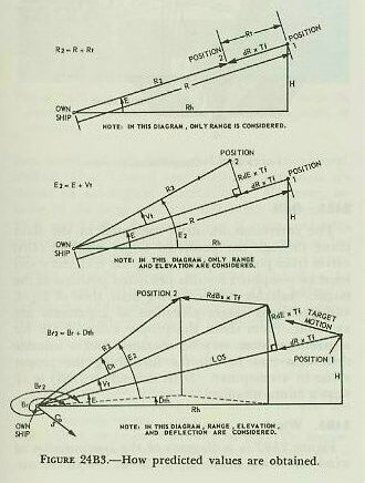
The predicted position of the target (see fig. 24B3) in relation to own ship is defined by the three coordinates:
1. Advance (or predicted) range R2.
2. Predicted relative target bearing Br2.
3. Predicted target elevation E2.
Note the numeral 2 is used to indicate predicted values describing the advance position. Approximate values for R2 and E2 are obtained by these equations:
R2=R +Rt.
E2=E+ Vt.
The expression for deflection prediction Dt= Tf/R2XRdBsXK is measured in the slant plane. The value for predicted relative bearing must be measured in the horizontal. Therefore, Tf XRdBs is divided by horizontal range, R2 cos E2, giving Dth. Consequently:

In the above equation, Rt does not take into account the fact that corrections for deflection and elevation have an effect on advance range; nor is the effect of a deflection setting on elevation shown in the expression for Vt.
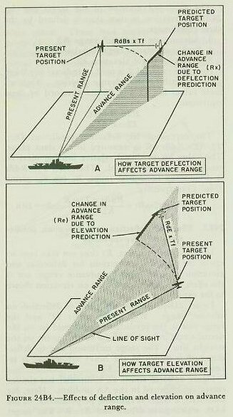
Figure 24B4(A) shows the effect of deflection on advance range. With target angle 90degrees and the range rate 0, the predicted range would lie on the dotted circle instead of at the desired point on the straight line. The range correction due to deflection rate is shown by the heavy arrow, and is labeled Rx.
Figure 24B4(B) shows an additional but similar correction required in the AA problem. Here, for simplicity, a target is climbing perpendicular to the LOS, which gives dR=O and Rt=0. The target again follows a straight course, so the error is the difference between the straight line and the circle, again shown by a heavy arrow and labeled Re. This is the range correction due to an elevation rate.
Although the angle made by the target and the LOS in both instances was taken as 90°, it should be evident that the two effects described will be present no matter what the target angle may be.
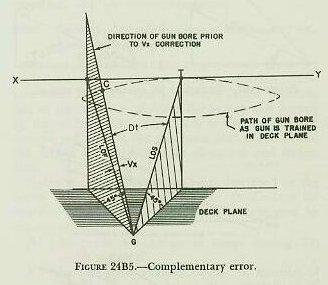
Figure 24B5 shows another error of size large enough to need correction in the AA problem. It is called complementary error and is the change in elevation caused by the deflection prediction (Dt) and E. Assume the target, T, is at the elevation 45° and is flying on a straight course at right angles to the LOS along XY. The figure shows that if a train correction only were made to compensate for target deflection the predicted LOF (GC in the figure) would not run to the target, but would pass above it. The deflection of the target has made necessary a smaller angle of elevation. This change in elevation is complementary error (Vx), and occurs because the gun’s roller path is in the deck plane, and, as the gun is trained, its bore axis follows the path of a cone. Vx is always a negative correction.
24B4. Correction for effect of gravity
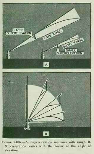
As in the surface problem, it is clear that the gun cannot be pointed directly at the advance target position, because the pull of gravity on the projectile during the time of flight will cause the trajectory to curve downward. The correction for gravity effect in the air problem is called superelevation (Vf). The angle the gun must be elevated to compensate for the effect of gravity depends on three factors: range, initial velocity, and target elevation. Superelevation varies inversely with I. V., because an increase of I.V. decreases the Tf for a given range, and gravity has less time to act. Superelevation increases with range, because range and time of flight are closely related. Superelevation varies as the cosine of the angle of elevation, decreasing as the gun is elevated. See figure 24B6. For a gun of given I. V., superelevation is considered to be a function of target elevation and range. In a computer, Vf is computed by a cam.
24B5. Drift
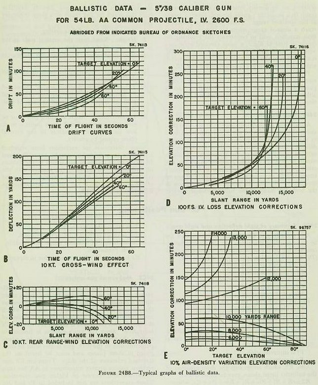
The correction for drift measured in the slant plane through the predicted target position (Dfs) varies from point to point along the trajectory and must be computed for this predicted position of the target. Suitable curves, having drift, time of flight, and predicted target elevation as arguments are available. From these, the proper value of Dfs for a given problem may be obtained and a suitable drift cam may be cut for furnishing the proper value in a computer. Drift correction (Dfs) is always a minus quantity.
24B6. Wind
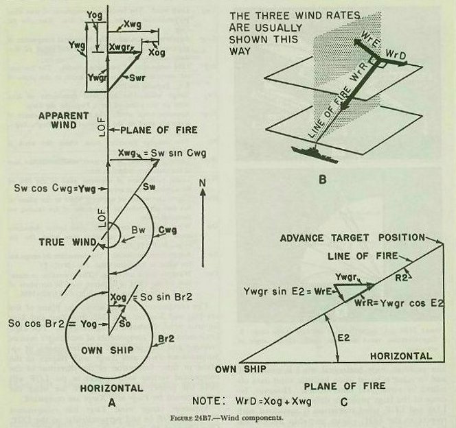
Figure 24B7 is a diagram of the computation of wind correction in the air problem. As in the surface problem, only horizontal wind is considered, and its value is based upon ballistic wind data obtained by aerological observations. However, because of the large probable difference between the LOS and LOF, wind correction is computed with respect to the LOF. Since own-ship motion has been considered as equivalent target motion in obtaining relative motion, apparent wind must be used in making wind corrections. The following definitions and symbols are essential to the computation and understanding of figure 24B7.
Cwg Predicted wind angle. The horizontal angle between the direction toward which the true wind is blowing and the plane of fire, measured clockwise from the direction toward which the wind is blowing to that part of the plane of fire between the wind and own-ship vectors.
Xog Cross component of own-ship velocity. The horizontal component of own-ship velocity perpendicular to the plane of fire. Xog=So sin Br2.
Xwg Cross wind. The horizontal component of true wind perpendicular to the plane of fire. Xwg=Sw sin Cwg.
Xwgr Apparent cross wind. The horizontal component of apparent wind perpendicular to the plane of fire. Xwgr=Xog+Xwg.
Yog Line component of own-ship velocity. The horizontal component of own-ship velocity in the plane of fire. Yog=So cos Br2.
Ywg Range wind. The horizontal component of true wind in the plane of fire. Ywg=Sw cos Cwg.
Bw The compass direction from which the wind is blowing.
WrD Linear component of apparent wind across the line of fire causing a deflection error.
WrR Linear component of apparent wind in the line of fire causing a range error.
WrE Linear component of apparent wind in the plane of fire and perpendicular to the line of fire causing an elevation error.
Dw Wind deflection correction. The lateral deflection angle to correct for apparent cross wind. Dw (in
mils)=WrDXTf/R2x563.
Rw Range wind correction. The correction in range for the effect of apparent wind. Rw=WrRXTJ.
Vw Wind elevation correction. The correction to elevation for the effect of apparent wind in the plane of fire. Vw (in minutes of arc) = WrEX Tf/R2x 1936
The components in and across the plane of fire are Yog and Xog for own ship, and Ywg and Xwg for true wind, as shown in figure 24B7. The algebraic sums of the components of own ship’s motion reversed and true wind are the components of apparent wind Ywgr and Xwgr with respect to the plane of fire. Inspection of the direction of the component vectors with respect to the LOF will yield the proper algebraic sign to use when the errors caused by Ywgr and Xwgr are computed.
Apparent range wind Ywgr has components WrR and WrE in and perpendicular to the LOF. One effect of WrR is to alter time of flight. As WrR opposes projectile motion, Tf is increased. Tf must be corrected for range wind. Another effect of WrR is to alter the range attained by the projectile when fired at a given angle of departure. A range wind correction, Rw, will correct for this error. It is evident that to obtain a given range with WrR acting against the projectile a greater angle of elevation and a greater time of flight are required.
The component WrE will also influence the trajectory. If the target is at high elevation and the wind is blowing against the projectile toward the gun, WrE will tend to elevate the trajectory. A correction to gun elevation called, Vw, wind elevation correction, must be applied to counteract the error caused by WrE.
The apparent cross wind component, WrD, causes deflection of the projectile. Wind deflection correction, Dw, is applied to sight deflection to compensate for this effect.
2487. Corrections for I. V. variations
Not all projectiles can be fired at the designed initial velocity, because of gun erosion and changes in temperature of powder charges. An altered I. V. will change the trajectory, in that a projectile fired below designed I. V. will travel more slowly and will drop sooner than a projectile fired at or above designed I. V. Two corrections are necessary, Rm, range correction for I. V. variations, and Vfm, elevation correction for I. V. variations. Rm is a function of I. V. variation and time of flight. Vfm is a function of I. V. variation, R2 and E2.
24B8. Correction for air density variation
Air density higher than standard would result in a projectile’s falling short of a desired range; or, in contrast, an air density lower than standard would result in a projectile’s going beyond, (over) a target at the specified range. Then, to have a projectile reach a desired range when air density is higher than standard, and to counteract the resulting increase in time of flight, a more elevated trajectory would be required. The elevation correction, Vu, is a function of the percent of variation from standard air density; and is a function of R2 and E2.
Practically, this correction does not exist in the mechanical solution of the AA problem. It is computed from a range table or nomogram and is either entered as a spot or converted to I. V. variation.
A trajectory graph appended to OP 551, 2nd rev., shows the trajectories of the 5”/38 gun when fired at various angles of departure under standard conditions. Any variation from these conditions results in modifications of the trajectory. While it would be possible to make a similar graph for any other particular set of conditions, it is obviously impracticable to do so for a wide variety of sets of conditions. Instead, the graph as shown serves as the basis for many of the ballistics which correct for variations. Among items directly available from this graph for any point on a given trajectory are:
1. Time of flight and fuze setting.
2. Height. Read from the vertical scale at the left edge of the drawing.
3. Horizontal range. Read from the range scale at the bottom.
4. Slant range. Obtained by using dividers and the horizontal range scale.
5. Target elevation (position angle). Measured by laying straight edge through origin and point on trajectory, and reading angle of position scale.
6. Superelevation. Angle at which gun must be elevated above predicted target position to al. low for trajectory curvature in the vertical plane caused by gravity.
Some corrections for variations from standard conditions are provided on graphs, generally about 18 inches by 24 inches in size, issued by the Bureau of Ordnance. To acquaint the student with the type of information available, excerpts from some of the graphs for the 5”/38 gun are reproduced in miniature in figure 24B8.
