US NAVY
FIRE CONTROL PAGES
NAVAL ORDNANCE AND GUNNERY
VOLUME 2, FIRE CONTROL
CHAPTER 25
LINEAR-RATE ANTIAIRCRAFT
FIRE CONTROL SYSTEMS
Chapter 25 Linear-rate antiaircraft fire control systems
A. General description
B. Director
C. Computer
D. Mark 6 stable element
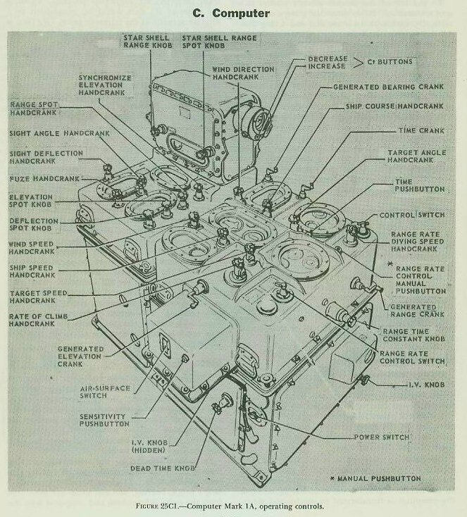
25C1. General
This section describes the Computer Mark 1A (fig. 25C1). The Computer Mark IA is the mechanical brain of the Gun Fire Control System Mark 37, which is used to control the fire of dual-purpose guns against both air and surface targets.
The Computer Mark 1A computes continuous gun orders containing corrections for all the significant factors affecting antiaircraft and surface fire. The corrections allow for motion of own ship and target during the time the projectile is in flight; for the curvature of the projectile path caused by gravity, drift, and wind; for pitch and roll of the ship; and for a number of other factors.
These gun orders, a fuze-setting order, and parallax corrections are continuously transmitted from the computer to the gun mounts. At the mounts, these orders are used to point the guns continuously, and to time the fuzes so that the projectiles will explode at the predicted position of the target.
Modifications of Computer Mark 1A have been developed to control the various calibers of dual-purpose guns in use in the Fleet. All modifications are essentially the same in appearance, function, and operation. They differ mainly with respect to the self-contained ballistic data which adapt them to a particular gun.
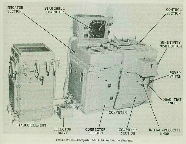
The Star-Shell Computer Mark 1, which is installed on top of the Computer Mark lA as an integral part, also will be described in this section. In this text, when the main computer is referred to it is called merely the computer. The auxiliary instrument is always called the star-shell computer. Both instruments are shown in figure 25C2.
The computer functions are:
1. To permit the dual-purpose guns to be pointed and trained, and fuzes and sights to be set continuously for either AA or surface fire against a common target.
2. To aid the director crew in keeping the line of sight on target in either air or surface fire.
3. With the star-shell computer, to permit the dual-purpose battery to be pointed and trained, and fuzes to be set continuously for illumination of a surface target.
4. To permit, as an alternative to 1, control of the 40-mm or 3”/50 rapid-fire guns at short ranges, and the main battery in barrage fire against a common target.
The computer makes nearly all of the calculations required for control of the dual-purpose battery that can be computed centrally. This permits standardization of equipment and increases the flexibility in multiple installations. It also permits the Mark 37 system to be used on any type of ship large enough to support its weight.
25C3. Outputs
The computer calculates and transmits the quantities listed below. Some are for both single and multiple installations, while some are for multiple installations only. Pv is used only on large carriers of the Essex and Midway types. Figure 25A3 shows graphically the distribution of most of the outputs. These outputs are supplied as follows:
Electrically to Guns
1. B’gr-Gun train order, automatic.
B’gr-Gun train order, indicating.
2. E’g-Gun elevation order, automatic. E’g-Gun elevation order indicating.
3. Ph-Train parallax for a 100-yard horizontal base.
4. Pu-Elevation parallax for a 100-yard horizontal base.
5. F-Fuze-setting order for mechanical fuzes.
6. Ds-Sight deflection.
7. Vs-Sight angle.
Electrically to Director
1. increments cB’r-Bearing correction, automatic.
increments cB’r-Bearing correction, indicating.
2. increments cE+ L +Zd/30-Elevation correction, automatic.
increments cE+L + Zd/30-Elevation correction, indicating.
3. increments cR-Range correction.
4. Ph-Train parallax for a 100-yard horizontal base (multiple installations only).
Mechanically to the Star-Shell Computer
1. B’gr-Gun train order.
2. E’g-Gun elevation order.
3. R2-Advance range.
4. WrD KRdBs-Star-shell deflection rate.
Mechanically to the Stable Element
1. B’r-Director train.
In the list above, where the same signal is transmitted both in automatic and in indicating, the signal is identical. It is sent over separate circuits following different paths to separate synchro receivers at the directors or mounts. This feature enables one transmission line to be used if the other is damaged. One controls the power drive and the other moves indicator dials. Use of the circuits can be exchanged, should the need arise, by suitable switching arrangements at the fire control switchboard.
Elevation parallax for a vertical base (Pc) is included in sight angle (Vs), and therefore in gun elevation order (E’g). It does not exist as a separate quantity.
25C4. Inputs
The computer receives the following inputs from the sources and by the methods indicated:
Mechanically from Stable Element
1. L-Level (or Lj-selected level).
2. Zd-Crosslevel (or Zdj-selected crosslevel).
3. L Zd/30-Level plus crosslevel function.
Electrically from Director
1. Eb-Director elevation.
2. B’r-Director train.
3. R-Observed present range (may be received by phone).
4. Dj-Deflection spot (may be received by phone).
5. Vj-Elevation spot (may be received by phone).
6. Rj-Range spot (may be received by phone).
7. Rate control or on target signals for range, elevation, and bearing.
Electrically from Gyro Compass and Pitometer Log
1. Co-Own-ship course.
2. So-Own-ship speed.
By Phone from Director, Put in Manually
1. A-Target angle, initial or corrective value.
2. Sh-Target’s horizontal speed, initial or corrective value.
3. dH-Rate of climb, initial or corrective value.
Manually: Calculated or Estimated in Plotting Room
1. As an alternative to 7, above, rate control values for range.
2. dR-Direct range rate (target diving speed).
3. Bw-True direction true wind.
4. Sw-True wind speed.
5. jBr-Initial relative target bearing.
6. jE-Initial target elevation.
7. jR-Initial range.
8. I. V.-Initial velocity.
9. Tg-Dead time.
10. Dip angle (by setting R2).
25C5. Principles
A detailed discussion of the principles of basic mechanisms used in mechanical computers has been given in section E of chapter 19. The present section provides a brief description of the calculations made within the computer.
The computer solution of the AA problem is in many respects similar to the solution of the surface problem by the rangekeeper described in chapter 19. The computer computes relative target motion rates which are used in generating cR, cBr, and cE. The effects of changes in Co are taken into account in the case of cBr. Since the computer was developed before radar became reliable, it was designed for rangefinder ranges. Because range-finder ranges are somewhat erratic at best, the computer used generated range (CR) for its calculations. This improves the smoothness of operation of the instrument. Measured relative target bearing (Br) and target elevation (E) are used for computations, because they can be measured accurately and smoothly. The target elevation (E) is obtained by subtracting level (L) from director elevation (Eb). (E=Eb-L). Relative target bearing (Br) is obtained by adding deck-tilt correction (jB’r) to director train (B’r). (Br=jB’r+B’r.)
Also, in keeping with methods used in the surface rangekeeper, the computer generates increments of range, relative bearing, and elevation (increments cR, increments cB’r, and increments cE). increments cB’r is sent to the director train receiver-regulator to move the line of sight according to the generated value of director train. It takes into account both deck-tilt correction and changes of own ship course. Thus, if the solution is correct increments cB’r will keep the line of sight on the target in train while the ship rolls, pitches, and changes course. As explained in article 25B9, this is only when the director train power drive is in automatic. increments cB’r, when used as described above, is called bearing correction. increments cE is added in the computer to level correction (L) and crosslevel function (Zd/30). The sum (increments cE+L+Zd/30) is called elevation correction. It is sent to the director elevation receiver-regulator to hold the line of sight on target in elevation. This it will do only if the director elevation power drive is in automatic and if the computer solution is correct.
These changes in director train and elevation caused by bearing and elevation corrections show up in new values of director train (B’r) and director elevation (Eb). Thus there is a continuous feed-back into the computer, since the director transmits B’r and Eb continuously to the computer. In other words, the computer and director together form a regenerative group. This allows the director to follow an obscured target by riding the computer solution. As long as the solution is correct, the director will remain on the target. This regenerative arrangement also permits indirect fire against a temporarily obscured target. This is accomplished in a manner similar to that described in chapter 19 for a surface rangekeeper. In addition, the computer is so arranged that generated bearing (cBr) can be used for calculations in surface fire. When this arrangement is used, the computer is regenerative in bearing within itself and can control indirect fire without director inputs.
Ballistics, too, are computed in the same manner in the computer as they are in the surface range-keeper. That is, the three linear rates (dR, RdE, and RdBs), generated present range (cR), and certain other necessary quantities are used. Actually, the computer develops advance range (R2) and predicted target elevation (E2) by a series of approximations. Using the advance target position, computations of ballistics are essentially the same as those developed in section 24B.
Because approximations are used in the computer, certain variations from the analytical solution exist. Some of these are:
1. Wind computations are empirical equations, based on an approximation of the line of fire.
2. Air-density corrections are separately computed, and applied to the computer as a change in initial velocity.
While the standard new-gun initial velocity for the 5”/38 gun is 2,600 foot-seconds, the computer calculations are based on an I. V. of 2,550 foot-seconds. This reduces the size of the maximum corrections which may have to be applied, and thus increases the accuracy of the average correction. Corrections may be automatically calculated for any variation of initial velocity between the standard (2,600 fs) and the lower limit (2,350 fs) which is set into the computer.
-The elements considered in the computation of sight angle, sight deflection, and fuze-setting are:
Vs-Sight angle
1. Vt-Elevation prediction.
2. Vf-Superelevation.
3. Vw-Wind elevation correction.
4. Vfm-Initial velocity elevation correction.
5. Vx-Complementary error.
6. Pe-Elevation parallax correction for a 30-foot vertical base.
7. Vj-Elevation spot.
Ds-Sight Deflection
1. Dt-Deflection prediction.
2. Dfs-Drift.
3. Dw-Wind deflection correction.
4. Dj-Deflection spot.
F-Fuze Setting
1. Tf-Time of flight.
2. Tg-Dead time.
The basic gun train and elevation orders have been discussed in chapter 24. Briefly, gun train order (B’gr) is equal to director train (B’r) plus deck deflection (Dd). (B’gr=B’r+Dd.) Deck deflection is equal to partial deck deflection (jDd) and trunniontilt train correction (Dz). (Dd=jDd+Dz.) Gun elevation order (E’g) is equal to director elevation (Eb) plus sight angle (Vs) minus trunnion-tilt correction in elevation (Vz). (E’g=Eb+ Vs-Vz.) B’gr is corrected for horizontal parallax (Ph) at the gun, while E’g, as transmitted by the computer, includes the correction for vertical parallax (Pe). On large carriers, E’g is further corrected at the guns for vertical parallax caused by horizontal displacement (Pv).
25C6. Rate control
1. General. As previously explained, the computer determines the relative motion rates (dR, RdE, and RdBs) from the primary data indicated below:
a. Estimated or computed: target angle (A), target horizontal speed (Sh) and rate of climb (dH).
b. Measured: Present range (R), relative target bearing (Br), target elevation (E), own-ship speed (So), own-ship course (Co), and time (T).
From these relative motion rates, generated target positions is computed (cR, cBr, and CE). Since the relative motion rates as well as the generated or computed value of range (CR) are used in the calculations for ballistics and predictions, it is necessary that these values be accurate for gun orders to be correct.
If the primary data listed above are correct, the relative motion rates will be correct and the generated target position values (cR, cBr, and CE) will agree with the observed target position values (R, Br, and E). If the primary data are not correct, however, the relative motion rates will be incorrect, and the generated target position values will not agree with the observed target position values; consequently gun ballistics and predictions and, therefore, gun orders will be in error.
Since the measured quantities of the primary data are determined by instruments, their accuracy is relatively high; consequently, whenever there is disagreement between generated and observed values of present target position, the likeliest source of error is in the quantities A, Sh and dH.
By adjusting the quantities A, Sh, and dH, the relative motion rates (dR, RdE and RdBs) can be corrected, bringing cR, cBr and cE into agreement with R, Br and E. The method by which this is accomplished is known as rate control.
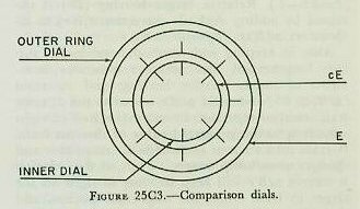
It is a simple matter to arrange a set of dials that will indicate disagreement between the actual and computed values of range, bearing, and elevation. For example, consider target elevation, and assume a dial group like that in figure 25C3. The outer ring dial is driven by measured or actual target elevation (E). The computer, receiving director elevation (Eb) from the director, combines Eb with level angle (L) in a differential to produce target elevation, one use of which is to drive the observed elevation dial. The inner dial is driven by generated target elevation (cE) as determined by the computer.
As the director LOS follows the target, changes in target elevation will obviously cause the outer ring dial to rotate. The speed of rotation will be proportional to the actual elevation rate. Changes in generated elevation drive in the inner dial at a speed proportional to the computed elevation rate (RdE). Equal rotational speeds of the outer ring dial and the inner dial are apparent when the inner dial marks remain stationary with respect to the outer ring dial marks. This condition signifies that the computed elevation rate equals the actual elevation rate. When the dials turn at different speeds, the computed rate (RdE) is evidently wrong and must be corrected by correcting the quantities A, Sh and dH. This same process can be applied to compare the computed and actual range and bearing rates.
Rate controlling can be accomplished with the director in automatic, local, or manual drive operation. Since operation of the director in automatic provides optimum use of the rate control features of the Computer Mark 1A, the ensuing discussion will consider the rate control features of the director with its power drives in automatic.
In this condition, increments cR, increments cB’r, and increments cE+L+Zd/30 will keep the director automatically on the target without handwheel motion by the pointer and trainer as long as the solution remains correct. Also, the rangefinder wander marks will keep on the target and the radar target pip will remain in the range notch.
If the solution is not correct, it is necessary for the director pointer and trainer to use their hand-wheels, with their rate control key depressed, to keep the LOS on the target. If the LOS gets off the target, the rate control keys should be released, and should not be closed until the crosswires are back on target. Rate control keys should be closed only when the crosswires are on target. Similarly, if the solution is not correct, the rangefinder operator and radar operator will have to use their range controls to keep the wander mark on target and the pip in the notch. While on target in range, the rate control keys should be depressed. However, if the operators get off in range, the rate control keys should be released until the operators get back on target.
2. Rate control symbols. In addition to the symbols previously covered in the course, the follow ring symbols are used in the analysis of rate control:
jBr-~Angular bearing rate correction.
jE-Angular elevation rate correction.
idR-Direct range rate correction.
These values represent the angular differences between the generated and observed changes in bearing and elevation and the linear difference between generated and observed range, and they are used in the rate control mechanism to correct the quantities A, Sh, and dH. When jBr and jE are multiplied by a value of range (as will be explained later) they provide the linear bearing and elevation rate corrections applied to the rate control mechanism:
jBc-Linear bearing rate correction. The rate correction primarily affecting linear deflection rate (RdBs).
jEc-Linear elevation rate correction. The rate correction primarily affecting linear elevation rate (RdE).
As will be explained in article 25C7, jdR in the slant plane is converted to the horizontal plane, resulting in the following quantity:
jdRh-Horizontal range rate correction. The rate correction primarily affecting horizontal range rate.
The following symbols will be used to represent the final rate control mechanism corrections to A, Sh, and dH.
jSh-Target horizontal speed correction. jHc-Rate-of-climb correction.
jCt-Target angle (course) correction. jRc-Linear range correction.
3. Methods of rate control. In the Computer Mark 1A, provision is made for two methods of rate control. These are automatic and manual rate control. Automatic rate control is made possible by the inclusion of a rate control computing mechanism in the computer. When employed, this mechanism will compute and correct the target motion rates A, Sh, and dH for targets at speeds of 15 knots to 800 knots. The rate control mechanism is not designed to operate accurately below target speeds of 15 knots; hence for the lower-speed targets, manual rate control should be employed.
Selection of the method of rate control is made at the computer by positioning the control switch and the range rate control switch. The control switch governs the method of bearing and elevation rate control. The range rate control switch governs the method of range rate control.
a. Automatic rate control. Automatic rate control is the normal method of operating Computer Mark lA for all air targets and for surface targets at speeds of 15 knots and over.
In automatic rate control, follow-up motors in range, bearing, and elevation are employed to keep the generated dials continuously rotating at the same rate as the observed dials. Figure 25C4 shows the flow diagram for bearing and elevation. Br and E are obtained from inputs of director train and elevation (Br B’r+jB’r and E=Eb-L). increments cBr and increments cE are obtained from the computer tracking section and increments cE=~T (dE)].
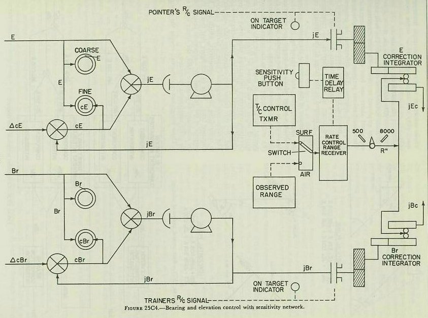
When the director operators close the rate control keys, the signal not only is transmitted to the computer ON TARGET indicators, but also is used to close clutches between the output shafting of the follow-up motors and the input shafting to the rate control mechanism. The jBr clutch and jE clutch are shown on figure 25C4. Thus when the director rate control keys are closed and an error exists in the computed rates (dR, dBr and dE), the output of the follow-up motors will drive into the rate control mechanism.
In this manner, when an error exists, the rate control mechanism automatically receives the rate corrections jdR, jBr, and jE, the differences between the rates of change of generated and observed range, bearing, and elevation. The rate control mechanism then will correct the values of A, Sh, and dH, thereby causing the computer to compute new target motion rates (dR, dBr, and dE). The new target motion rates will result in new values of increments cBr, and increments cE to drive the generated dials. In addition, since target motion rates are used in the computer prediction and correction sections, the computer will compute new and more accurate gun orders.
b. Manual rate control. Manual rate control must be used when the rate control mechanism is inoperative, for indirect fire when observation of the target is impossible, and for surface targets below a speed of 15 knots. In this method, initial values of target angle, target horizontal speed, and target rate of climb must be estimated and set manually into the computer. When the director rate control keys are closed, signals appear at the computer ON TARGET indicators. Computer personnel then know that the director is on target and the correct values of R, Br, and E are indicated on the comparison dials. If the generated dials are not rotated at the same speed as the observed dials, the initial estimates of A, Sh, and dH were incorrect, and are changed manually until all comparison dials are rotating together. In addition, the computer range operator must ensure that the correct value of range is continuously set on the range dials.
It should be evident that initial estimates of A, Sh, and dH depend upon the skill of the control officer. Even the most experienced officers cannot estimate these values within close enough limits to ensure accuracy of the solution; consequently a correct solution generally requires changing manually the initially estimated values. For this reason, and because of the short duration of the air problem, manual rate control is considered an auxiliary type of operation for air targets.
1. Analytical solution. The function of the rate control mechanism is to correct the values A, Sh, and dH. By analyzing the differences between changes in generated and observed values of range, bearing, and elevation (jdR, jBr, and jE), this mechanism determines what errors in A, Sh, and dH were responsible for such differences, and corrects the errors. Once A, Sh, and dH are corrected, the computed relative motion rates should be correct and, therefore, the gun orders should be accurate.
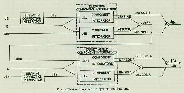
Figures 25C5 and 25C6 show analytically and by flow diagram how the rate control mechanism solves the problem. In studying the figures, the following symbols are used:
jBr-Angular bearing rate correction. jBc-Linear bearing rate correction.
jE-Angular elevation rate correction. jEc-Linear elevation rate correction. jdR-Direct range rate correction.
jdRh-Horizontal range rate correction. jSh-Target horizontal speed correction. jHc-Rate-of-climb correction.
jCt-Target angle (course) correction.
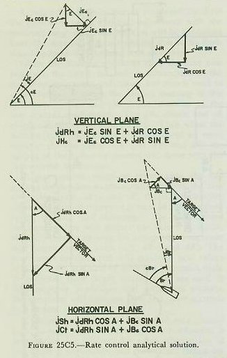
Since the basic mechanisms employed in the rate control mechanism require linear inputs, the angular bearing and elevation rate corrections (jBr and jE) must be converted into linear bearing and elevation rate corrections (jBc and jEc). As shown in figure 25C5, the linear rate corrections in the vertical plane through the line of sight (jEc and jdR) are resolved into horizontal and vertical components. The horizontal components are combined to produce horizontal range rate correction (jdRh). The vertical components are combined to produce rate-of-climb correction (jHc). The latter correction, jHc, is used to correct target rate of climb (dH).
jdRh=jEc sin E+jdR cos E.
jHc==jEc cos E+jdR sin E.
These values are used to correct target horizontal speed (Sh) and target angle (A) or target course (Ct).
jSh=jdRh cos A+jBc sin A.
jCt=jdRh sin A+jBc cos A.
2. Basic mechanisms employed. The basic mechanisms employed to resolve the rate corrections as explained above are four component integrators. These mechanisms perform the same functions as component solvers. The differences in construction, however, enable the component integrator to handle rapidly changing inputs throughout an unlimited range of values, whereas the component solver is limited in the range of the inputs it can handle.
The inputs of the component integrator, a changing angular value and a changing linear value, establish a vector which has length and direction. As shown in figure 25C6, the angular input to the elevation component integrators is target elevation (E), and the angular input to the target angle component integrators is target angle (A). Since the second input to each must be linear, bearing and elevation correction integrators (disc type) are employed to convert the angular rate corrections (jE and jBr) into linear rate corrections (jEc and jBc). The correction integrators have a further function in controlling computer sensitivity, which will be discussed later. Note in the figure that two of the outputs of the jdR and jEc component integrators are combined to produce jdRh, the linear input to the jdRh component integrator.
These integrators continuously resolve the changing vector into sine and cosine functions of the vector input. The sine and cosine functions are combined into the required corrections, jCt, ySh, and jHc, as indicated in the figure. As previously stated, when A, Sh, and dH are corrected, new values of dR, RdE, and RdBs are computed which give more accurate gun orders.
25C8. Computer sensitivity
The rate control system of Computer Mark 1A includes sensitivity units which control the time required by the computer to reduce errors in generated rates to the point where the corrected rates are sufficiently accurate to compute adequate gun orders. Sensitivity may be thought of as the speed with which the errors are corrected by the rate control mechanism. If the errors are corrected within a relatively short time interval, the sensitivity is considered to be high, and if the errors are corrected within a relatively long time interval, the sensitivity is considered to be low.
The time interval used is called the time constant (Tc), and is defined as the time in seconds required to reduce a rate error to an acceptable figure, or 37% of its initial value. Thus a low time constant will give high sensitivity, and a high time constant will give a low sensitivity. For example, assume a direct range rate error (jdR) of 100 yd/sec, and accurate ranging by the rangefinder or radar operator. If the Tc is 2 seconds, the 100 yd/sec error would be reduced to a 37 yd/sec error in 2 seconds, and the sensitivity of the range rate network would be considered high. In the next 2 seconds, the 37 yd/sec error would be reduced further to approximately a 14 yd/sec error (37% x 37).
If the Tc is 16 seconds, the 100 yd/sec error would be reduced to a 37 yd/sec error in 16 seconds, and the sensitivity of the network would be considered low. In the next 16 seconds, the 37 yd/sec error would be reduced further to approximately 14 yd/sec error (37% X 37). Thus the time constant can be used as an indication of the system sensitivity, or the speed with which it arrives at a solution accurate enough to compute adequate gun orders.
High sensitivity is desirable in a computer so that large rate errors may be corrected rapidly, as when first acquiring a target or when the target maneuvers radically. On the other hand, too high a sensitivity results in instability in computer operation; if the rate of correction of a given rate error is too high, momentary overcorrection of the error results, and oscillation of computer solution is encountered. Furthermore, at long ranges particularly, the rate errors detected may be in large part due to tracking errors. To use too large a rate correction in this case would result in correcting the problem for an error that does not exist; again, unsatisfactory results would be obtained. Consequently, the sensitivity networks are designed with two points in mind: (1) the rate control mechanisms use, as inputs, values of jEc, jBc, and jdR that are something less than the actually detected rate errors; and (2) provision is made in the mechanism design for varying the ratio of the rate error used to that of the rate error detected, so that the time constant, or sensitivity, is variable and adjustable (within limits).
Functionally, the sensitivity network of Computer Mark lA is composed of two separate parts:
(1) control of the sensitivity of the range rate control network and (2) control of the sensitivity of the bearing and elevation rate control network.
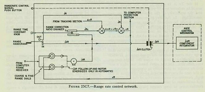
1. General. Control of the sensitivity of the range rate control network enables the computer range operator to use large direct range rate corrections (jdR) when the range rate errors are large, and small direct range rate corrections (jdR) when the range rate errors are small, by varying the time constant of the network and hence the sensitivity. Before discussing how this is accomplished, however, it is necessary to understand the operation of the network. Figure 25C7 shows the units employed in the range rate control network.
2. Operation. The director transmits to the computer range receiver a value of observed range (R) which is sent to the inner coarse and fine computer range dials (shown in the figure). The outer (ring) coarse and fine range dials are driven by a value of generated range (CR). If the computed range rate (dR) is correct, the R and cR dials will change (rotate) at the same rate. In addition, since all range lines in the computer are positioned by a value of generated range, cR must be exactly equal to R whenever R is correct.
Operation of the network is governed by the position of the range rate control switch, which has two positions: AUTO and MANUAL.
a. AUTO position. Normal computer range operation is obtained with the range rate control switch positioned to AUTO. The R and cR dials continuously are kept matched and rotating together by the jdR follow-up and motor shown in figure 25C7. A special contact arrangement between the dials controls the motor which drives the difference between R and cR through a range correction ratio changer into the cR line. The linear correction to cR, shown in the figure, is called linear range correction, jRc.
Whenever either the director rangefinder operator or the radar range operator depresses his director rate control button (not shown in figure), the jdR clutch is energized (closed), and a value proportional to the difference between R and cR is also driven into the rate control mechanism as direct range rate correction, jdR.
b. MANUAL position. Whenever the range rate control switch is positioned to MANUAL, the computer range operator must perform the function of the jdR follow-up motor by rotating the range handcrank. With the range handcrank in the OUT position, the computer range operator matches the generated range dials with the observed range dials. In so doing, he introduces initial range (jR) into the computer. If the computer has been tracking a target, the tracking section has developed increments of generated range (increments cR), which are combined with jR to produce generated range (cR). As shown in the figure, cR is used both in the computer prediction section and to position the cR dials.
With the range handcrank at the IN position, the computer range operator can still match the generated range dials with the observed range dials, though at a much slower rate, since the input must pass through the range correction ratio changer.
As shown in figure 25C7, whenever the computer range operator rotates the range handcrank in the IN position to keep the cR dial rotating at the same rate as the R dial, and at the same time pushes the computer range rate control manual push button, the jdR clutch is energized (closed), and a value proportional to the difference between R and cR is driven into the rate control mechanism as jdR.
3. Sensitivity control. The range correction ratio changer is a disc-type integrator whose function is to control the amount of direct range rate correction (jdR) going into the rate control mechanism for any given amount of linear range correction (jRc). The disc of the mechanism is turned by direct range rate correction (jdR). The carriage is positioned directly by the range time constant knob on the front of the computer. The roller drives linear range correction (jRc) into the cR line.
It should be remembered that the output of a disc-type integrator depends both on the input to the disc and on the position of the integrator carriage on the disc. With the carriage near the center of the disc, the roller output will be minimum. With the carriage at the periphery (edge) of the disc, the roller output will be maximum.
A sleeve on the range time constant knob is graduated from 0 to 16 seconds. As previously stated, the time constant represents the time in seconds required to reduce a given rate error to 37% of its initial value, and is a measure of the sensitivity of the network. The setting on the RTC knob determines the amount of direct range rate correction (jdR) introduced into the rate control mechanism for each unit of linear range correction (jRc) applied to generated range (cR).
Suppose generated range (cR) needs a correction (jRc) which requires ten turns of the integrator roller. If the range time constant knob is at the
1-second position, the integrator carriage is positioned near the center of the disc; hence relatively many turns of the disc (by the input jdR) are needed to turn the integrator roller the ten revolutions to produce the required amount of jRc. A relatively large jdR, therefore, is applied to the rate control mechanism (if the jdR clutch is energized) for the jRc needed to match the range dials.
If the range time constant knob is at the 16-second position, the integrator carriage is positioned near the periphery (edge) of the disc; hence relatively few turns of the disc (by the input jdR) are needed to turn the integrator roller the ten revolutions to produce the required amount of jRc. A relatively small jdR, therefore, is applied to the rate control mechanism (if the jdR clutch is energized) for the jRc needed to match the range dials.
By positioning the range time constant knob, the computer range operator controls the sensitivity of the range rate control network. By selecting a small RTC setting, a large value of jdR can be applied to the rate control mechanism. By selecting a large RTC setting, a small value of jdR can be applied to the rate control mechanism. In practice, the computer range operator should keep the setting of the range time constant knob as low as possible without causing instability in the computer solution.
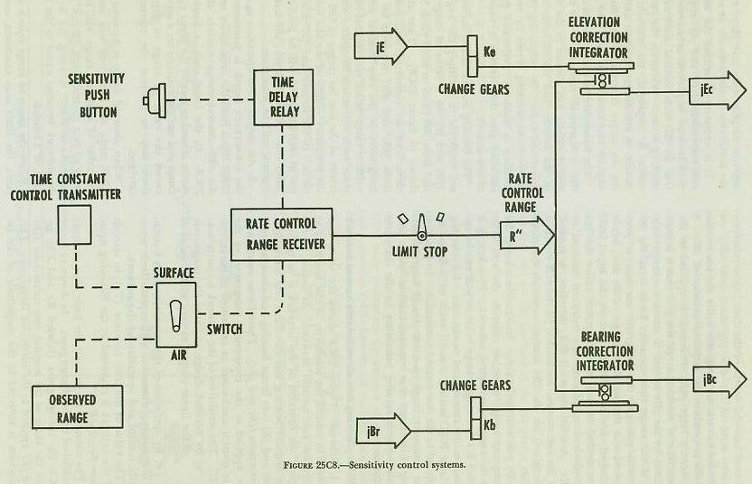
1. General. Figure 25C8 shows the units employed to control the sensitivity of the bearing and elevation rate control network. As shown in the figure, the function of the network is to convert the angular bearing and elevation rate corrections (jBr and jE) into linear bearing and elevation rate corrections (jBc and jEc). These linear corrections are applied to the component integrators of the rate control mechanism as explained in paragraph 25C7. The sensitivity of the network is controlled:
a. By network design to cause the magnitude of the linear output to vary with a value of range.
b. By operation of the sensitivity push button.
The ensuing discussion will explain both sensitivity control and operation of the network.
The value of the time constant (Tc) in seconds for the network is expressed by the following equation: Tc=2XR/R”.
The constant 2 represents the basic time constant established by the change gears. As shown in figure 25C8, the change gears (labeled Ke and Kb) reduce the value of the angular rate corrections (jBr and jE) applied to the correction integrator. This reduction is reflected in the magnitude of the integrator outputs (jBc and jEc), and hence affects the sensitivity of the network at all ranges.
It is necessary to reduce the measured angular rate corrections (jBr and jE) applied to the network in order to prevent overcorrection of the solution by the rate control mechanism due to the tracking errors. Whenever the rate control mechanism is employed, the amount of handwheel motion by the director pointer and trainer in staying on target determines the magnitude of the angular rate corrections (jBr and jE).
The handwheel motions contain tracking errors due to inaccurate tracking of the target in bearing and elevation, lost motion in the mechanical parts of the system, and maladjustment of the power drives and radar. By employing change gears, the effect of the tracking errors in overcorrecting the solution is reduced. Normally the change gears installed give the network a basic time constant of two seconds.
The bearing and elevation correction integrators are employed to multiply the angular corrections (jBr and jE) by a value of range (which is limited from 500 yards to 8,000 yards by the limit stop shown in figure 25C8). Thus the angular rate corrections are converted into linear rate corrections (jBc and jEc) required by the component integrators of the rate control mechanism. The value of range called rate control range (R”), positions each correction integrator carriage near the center of the disc for ranges of 500 yards, and near the periphery (edge) of the disc for ranges of 8,000 yards. In the former case (R”=500 yd), the output of each integrator will be minimum, and in the latter case (R”=8,000 yd), the output of each integrator will be maximum.
2. Air targets. For operation against air targets, the AIR-SURFACE switch is positioned at AIR. The range input from the rangefinder or radar activates the rate control range receiver shown in figure 25C8. In the latter unit, a single-speed synchro motor is used to receive the input value of observed range and to close contacts on a servo motor. This causes the value of range to drive through the limit stop to position the correction integrator carriages.
When observed range is between 500 yards and 8,000 yards, the limit stop will not function and the value of observed range will be equal to the value of rate control range (R=R”). Thus, since the ratio of R/R” is unity, the time constant for the network becomes equal to the basic time constant, or 2 seconds.
When the observed range equals or exceeds 8,000 yards, the limit stop functions, and the value of rate control range (R”) applied to the two correction integrator carriages remains at 8,000 yards. Therefore, for all air targets at a range of 8,000 yards and beyond, the value of the linear rate corrections (jBc and jEc) applied to the component integrators is a maximum. As can be determined from the time constant equation (Tc=2XR/R”), the time constant will increase uniformly as the range increases beyond 8,000 yards; hence the network sensitivity will commence to decrease uniformly beyond that range.
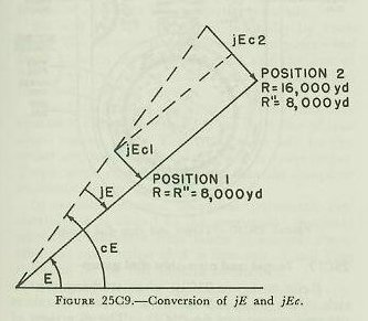
Since by design of the network jEci is applied to the component integrators at all ranges of 8,000 yards and beyond, it will take a longer time for the rate control mechanism to reduce the given angular rate error for a target at position 2 than at position
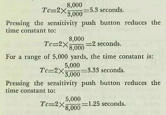
1. Note that for the ranges given in the figure jEc2=2XjEcl, and that the range at position 2 is twice the range at position 1. Since at position 2 only one half of the correct linear rate correction is being applied to the component integrators, it will take twice as long for the rate control mechanism to remove the entire jE correction for a target at position 2 as at position 1. This can be substantiated further by substituting the correct values of range in the network time constant equation (Tc=2XR/R”):


3. Surface targets. For surface targets, the AIR-SURFACE switch is positioned at SURFACE. When so positioned, it disconnects the rate control range receiver from the rangefinder or radar, and connects it to the time constant control transmitter. The latter unit is a synchro transmitter used to transmit a predetermined value of range to the rate control range receiver. This value is usually set at 3,000 yards, since experience has proved that the system operates best at this range for surface targets. Thus, as determined by the time constant equation, the time constant will increase uniformly at all ranges for surface targets, since R” is always 3,000 yards, unless the sensitivity push button is pressed.
In the latter case, R” becomes 8,000 yards for approximately two seconds, as explained above. For the surface problem, pressing the sensitivity push button will reduce the time constant at all ranges, and hence increase the network sensitivity. The following examples will illustrate how the time constant is affected by the sensitivity push button for the surface problem. If the observed range is 8,000 yards, the time constant is:
Computer Mark lA is built in four sections for ease of handling and assembling. These are: control section, indicator section, computer section, and corrector section. The first two are mounted on top of the second two in the order given. Figure 25C2 shows these four sections. The side nearest the stable element is the rear of the computer.
The control section contains the mechanisms for computing and controlling rates, and carries most of the knobs, cranks, and dials. The computer section (below the control section) contains the mechanisms that calculate the ballistics. The indicator section shows on dials and counters the end results of the ballistic calculations: sight angle (Vs), sight deflection (Ds), fuze order (F), and advance range (R2). Below the indicator unit, the corrector unit computes and indicates gun train order, gun elevation order, and parallaxes. Figure 25C1 shows many of these items, plus additional ones, some of which will be discussed later. Frequent reference to this figure in the following discussion will help the student to grasp the overall picture of the computer.
Many of the knobs and cranks have more than one position. Locking pins are provided to hold the cranks in the position desired. Some knobs have crank handles attached to permit rapid turning.
25C12. Target and own-ship dial group
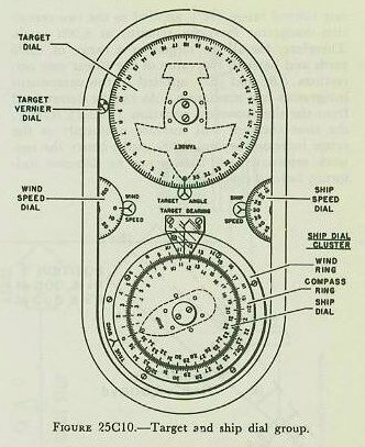
Refer to figure 25C10 when studying this article. This group is located on the control unit at the rear center (see fig. 25C1). The directions of wind, ownship, and target motions and the speeds of wind and own ship are indicated. Inscribed on the target dial, at the rear, are the outline of a plane and a compass rose. The own-ship dial group, at the front, has three concentric dials. On the inner dial are inscribed the outline of a ship and a compass rose. The intermediate ring dial has only a compass rose, while the outer ring dial has only an index mark. Between the target dial and the own-ship dial group is a pair of fixed indexes (in line with one another) representing the horizontal projection of the line of sight.
The target dial indicates only target angle (A) against the fixed index. The inner or ship dial of the front group reads relative target bearing (Br) against the fixed index. On the compass ring of the intermediate ring dial, own ship’s course (Co) is read against the bow of the ship outline of the inner dial. Also on the intermediate ring, true bearing (B) is read against the fixed index. The value of true direction of true wind (Bw) is determined by reading the intermediate-dial compass rose against the index of the outer ring. The student is reminded that Bw is the direction from which the true wind is blowing.
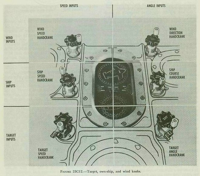
Bw and Sw are introduced manually by knob only. The instrument continuously computes wind angle between the wind direction and the line of fire. Thus the setting of Bw is changed only when the wind direction changes. See figure 25C12.
Introducing target angle (A) into the computer enables the computer to solve for the value of true target course (Ct) - This true course will be corrected continuously as in the surface rangekeeper. Target angle can be introduced into the computer automatically or manually.
In normal computer operation (automatic rate control), A is slewed to the proper 90 degree quadrant when the computer time motor is started; thereafter the exact value of A is determined and kept corrected by the rate control mechanism.
In manual computer operation (manual rate control), A is estimated by the director crew, phoned to the plotting room, and introduced manually into the computer; thereafter A is changed as necessary to obtain a correct solution.
The target angle (A) knob has attached to it a two-position shift lever labeled HAND and AUTO. To introduce A into the computer manually, the shift lever must be thrown to HAND. To permit changes of A by the rate control mechanism, the shift lever muse be thrown to AUTO. In addition, for the rate control mechanism to function, similar levers on the target-speed (Sh) knob and rate-of-climb (dH) must be thrown to AUTO.
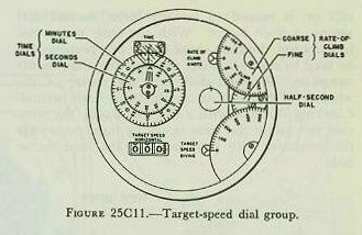
This group, under a single round window, is located at the right front of the control unit (fig. 25C2). Displayed are: dH in knots on a dial, Sh in knots on a counter, target-speed diving in knots on a dial, and time on two dials (fig. 25Cl1).
The rate-of-climb (dH) dial is at the right rear of the group. dH can be introduced manually, but normally is controlled by the rate control mechanism as described in article 25C7. The dH knob shift lever is thrown to HAND for manual operation and to AUTO for control of dH by the rate control mechanism.
At the left front of the window is the Sh counter which shows horizontal ground speed of the target in knots, from 0 to 800 knots. As with rate of climb, Sh can be introduced manually, but normally is controlled by the rate control mechanism as described in article 25C7. The Sh knob shift lever is thrown to HAND for manual operation and to AUTO for control of Sh by the rate control mechanism.
For tracking high-speed surface targets, a low elevation switch keeps dH equal to zero whenever E becomes less than 2 degrees. In manual computer operation (manual rate control) Sh and dH are estimated by the director crew, phoned to the plotting room, and introduced manually into the computer; thereafter Sh and dH are changed as necessary to obtain a correct solution.
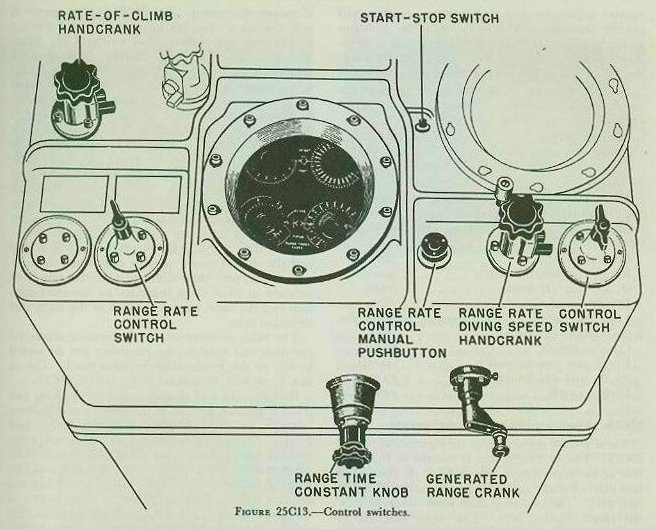
The right front dial of the group shows negative range rate or diving speed. It is used only for dive attacks. In such attacks the target moves virtually along the line of sight, making its total relative motion equal to negative dR. This rate is set on the dial manually by a special knob: the range-rate/diving-speed knob. See figure 25C13. This knob has a two-position lever like the A and Sh knobs. The lever is shifted to HAND (for dive attacks only) for manual operation. It is left at AUTO at all other times, so the rate control mechanism will be free to function as described in article
25C7.
The time dials located at the left rear of the window show time in minutes and seconds. The ring dial indicates minutes, while the inner dial reads seconds. Driven by the computer time motor, these dials are used in conducting maintenance tests. They can be set manually by the time crank. Pushing the crank IN causes the minute ring dial to return to zero automatically. Then the crank, still IN, is turned to set the inner, second dial against a fixed index. With the time motor not functioning, the time crank in the OUT position can be used to turn all shafts transmitting time in the computer. A small dial near the center of the window is designed to rotate twice each second. Checking this dial with a clock or watch, the operator can rotate the time crank by hand to supply the computer with time input if the time motor fails.
25C14. Control switches
There are two switches located at the computer range operator’s station on the front top edge of the control section as shown in figure 25C13. These switches are the control switch and the range rate control switch. They are used to select the method of rate controlling and computer operation.
The control switch has three positions: NORMAL, TEST, and LOCAL. Positioning the switch causes changes in the computer electrical circuits required by the methods of rate control for bearing and elevation and for operation of the computer without director inputs. With the control switch on NORMAL, bearing and elevation rate corrections are introduced into the rate control mechanism by the director trainer and pointer turning their handwheels with the rate control keys closed. This is the method of rate controlling called automatic rate control-discussed in paragraph 25C6 (3) (a)-and is employed against all air targets as well as surface targets at speeds of 15 knots or greater.
With the control switch in the TEST position, manual rate control only is possible. Changes in A, Sh, and dH (for air targets) are made manually by computer operators until the generated bearing and elevation dials are rotating at the same rate as the observed dials. This method of rate control must be used for targets at speeds below 15 knots as explained in paragraph 25C6 (3) (b). The rate control mechanism does not function with the switch at TEST.
With the control switch at LOCAL, director inputs are prevented from entering the computer, and the computer solution is based upon its own generated value of relative target bearing. This allows the computer to be used for indirect fire against a surface target when the target is not visible from the director. Range and target bearing are obtained from a source other than the director, such as combat information center, and entered manually into the computer.
The rate control mechanism does not function with the control switch at LOCAL. The range rate control switch has two positions: AUTO and MANUAL. Positioning the switch causes changes in the computer electrical circuits required by the methods for rate controlling in range and described in article 25C9. With the switch at AUTO, either the rangefinder operator or the radar operator in the director initiates the rate control corrections in the computer. With the switch at MANUAL, rate controlling in range is performed at the computer by the computer (range) operator. The rate control mechanism will function for either position of the range rate control switch unless the rate control mechanism is made inoperative by positioning the control switch at TEST or LOCAL.
While the control switch and the range rate control switch are not tied together, neither will permit the rate control mechanism to function properly unless the four shift levers are all at AUTO. These shift levers are on the A knob, the dH knob, the Sh knob, and the range-rate/diving-speed knob.
Normal operation of the computer employs the automatic rate control mechanism, and is obtained by the following switch positions:
Control switch...................... ..........NORMAL
Range rate control switch................AUTO OR MANUAL
A, Sh, dH, and diving-speed............ AUTO knobs.
Manual operation of the computer requires that the computer crew employ manual rate control methods, and requires the following switch positions:
Control switch...................................TEST
Range rate control switch...................MANUAL
A, Sh, and dH knobs...........................HAND
Diving speed....................................... AUTO
Local operation of the computer requires following switch positions:
Control switch.....................................LOCAL
Range rate control switch....................MANUAL
A, Sh, and dH knobs............................HAND
Diving speed....................................... AUTO
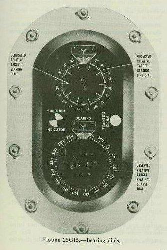
These groups are shown in the figures 25C14 and 25C15. The bearing group is located at the right rear of the control unit (fig. 25C2). It consists of two pairs of dials, each having an inner dial and a ring dial. The two ring dials show observed relative target bearing (Br). The coarse ring dial is graduated through 360 degrees, while the fine ring dial is graduated through 10 degrees of Br. The inner dial of the fine dial group has 10 equally spaced scribe marks only. This dial is driven by generated relative target bearing (cBr). When the control switch is at NORMAL or LOCAL, the cBr dial is driven by the bearing follow-up motors, which cause it to rotate automatically at the same rate as the fine Br dial. When the control switch is at TEST, these dials rotate together only when the computer solution is correct. Any difference in the speeds of rotation of these dials indicates an incorrect solution and the need for a correction to the computed bearing rate.
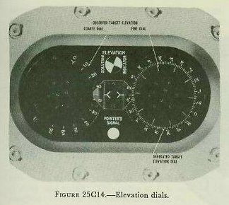
Located at the left rear of the control unit is the elevation dial group (fig. 25C2). This group is very similar to the bearing group except for the graduations and values used to drive the dials. The two ring dials (fig. 25C14) show observed target elevation (E). Within the fine-ring E dial is the inner dial inscribed with 10 equally spaced scribe marks only. This dial is driven by the values of generated target elevation (CE). The inner dial of the coarse-ring E dial is blank and does not rotate. When the control switch is at NORMAL, the cE dial is driven by an elevation follow-up motor which causes it to rotate automatically at the same rate as the fine E dial. When the control switch is at LOCAL, the elevation dials will show 00 target elevation, since the local position is used for surface fire only and there are no director inputs.
With the control switch at TEST, the fine E dial and the cE dial rotate together only when the solution is correct. Any difference in the speeds of rotation of these dials indicates an incorrect solution and the need for a correction to the computed elevation rate.
The value of observed target elevation shown on the dials and used in the computer can be varied by use of the synchronize-elevation knob. Use of this knob will be described in article 25C17.
Both bearing and elevation dial groups have two small indicators located at the edges about halfway between the ring dials. See figures 25Cl4 and 25C15. One of these indicators shows red when the rate control key in the director is closed. The other indicator is a dial having two black and two white quadrants. This indicator rotates when the director trainer (pointer) turns his handwheels in automatic rate control. It is called a solution indicator. A red signal and a moving solution indicator show that rate corrections are entering the computer’s rate control mechanism. As explained earlier, this statement is true only if the four shift levers are thrown to AUTO.
25C16. Range and height dial group
This dial group is shown in figure 25Cl6. It is located at the front center of the control unit (see fig. 25C2). It consists of two sets of dials-one for range and one for height. The two dials at the rear of this group show coarse and fine values of generated target height (cH). This quantity is not used in normal operation of the computer.
The range dials consist of two pairs of ring and inner dials. From left to right, the ring dials indicate coarse and fine values of generated present range (CR). Within each ring dial is a dial inscribed with a pointer only. From left to right, these dials are driven by coarse and fine values of observed present range (R). For proper operation of the computer, observed and generated present ranges must be equal, because the instrument uses cR for its calculations. When the range rate control switch is at AUTO, the range follow-up motor drives the cR dial to keep it matched with and rotating at the same rate as the R dial. When the dials are matched, the zero marks on the ring dials (cR) are opposite the pointers on the inner dials (R) as shown in figure 25C16. When so matched, the value of cR equals the value of R and can be read at the fixed indexes.
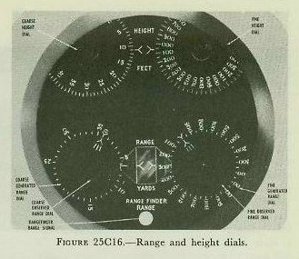
When the range rate control switch is at MANUAL, the range follow-up motor is de-energized, and the computer range operator, using the generated range handcrank, must match the cR dials with the R dials, thereby introducing the correct value of cR into the computer. If the computed value of range rate (dR) is correct, the R and cR dials will stay matched and rotate at the same speeds. If the computed value of range rate (dR) is not correct, the cR and R dials will not rotate at the same speeds, and consequently the dials will not remain matched. The computer range operator, then, must rematch the range dials and at the same time introduce range rate corrections into the rate control mechanisms. This is accomplished by turning the generated range handcrank and depressing the computer range rate control manual push button as explained in article 25C9.
The generated range crank has two positions- OUT and IN. At the OUT position, the crank introduces and corrects cR by turning the cR dials, but does not affect range rate. When the crank is IN, it accomplishes the same thing plus introducing range rate corrections if the range rate control manual push button is depressed.
The computer is limited mechanically to a maximum tracking range of 35,000 yards. Accordingly, the coarse cR ring dial is graduated only to 35,000 yards. When the computer range limit is reached, the cR ring dial stops, but the pointer on the inner R dial continues to turn. This indicates to the operator that the actual range is beyond the computer limit, and it gives some idea of what the target is doing.

This dial group and the associated knob are shown in figure 25C17. They are located on the indicator section just below the star-shell computer (see fig. 25C2). The function of the synchronize-elevation mechanism is to interrupt the computer elevation shafting in order to permit the Computer Mark IA to be used for methods of fire which can be employed against surface targets, but which usually are not practical against air targets. The ensuing discussion will explain the use of the synchronize-elevation mechanism in each of its three positions: IN, CENTER, and OUT.
1. IN position. With the synchronize-elevation knob in the IN position, the value of E used in the computing section of the computer is adjusted to the value of E obtained by combining L with Eb being measured by the director. This is done by matching the synchronize-elevation dials against the index (see fig. 25C17), which allows elevation (Eb-L) to drive through the differential (D-12) unchanged (see fig. 25C18). The synchronize-elevation knob is always placed in the IN position and the synchronize-elevation dial matched, except for special types of surface fire.
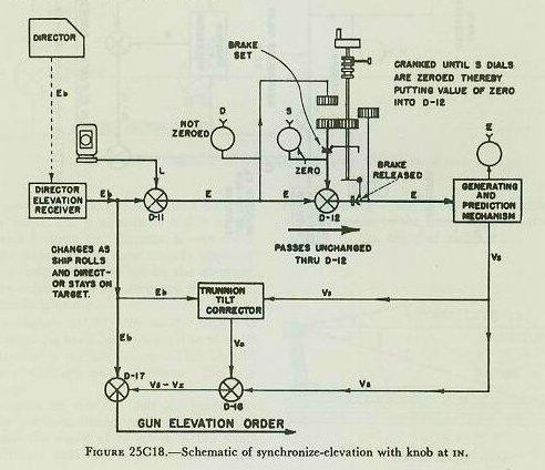
2. CENTER position. In certain special types of surface fire the quantity Eb minus L is not introduced into the computing mechanism. For example, using selected elevation aiming, the director sights do not continuously remain on the target, but are fixed in relation to the deck. When the line of sight is off target in elevation, the combination of fixed Eb and changing L produces inaccurate values E which must not be allowed to enter the generating and prediction mechanism.
Placing the synchronize-elevation knob in the CENTER position accomplishes two things. First, the inaccurate value of E is kept out of the generating and prediction mechanism by interrupting its transmission through the elevation shafting to the generating and prediction mechanism at differential
D-12. Secondly, the elevation shafting leading out of differential D-12 and into the computing section is positioned by turning the synchronize-elevation knob. The shaft is always positioned at zero elevation, because the actual surface target elevation is close to that value. This value of E is used in the computer only for the computation of Vs.
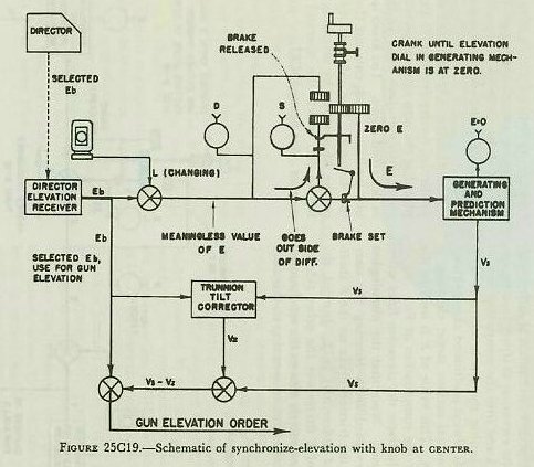
Figure 25C19 illustrates the elevation lines when a selected Eb is used. Note that the meaningless value of E is prevented from entering the computing section by the friction brake on the E shafting to the right of differential D-l2. Instead, the inaccurate value of E drives out the other side of differential D-l2 and merely rotates the synchronize-elevation dials, which have no meaning in this case.
The synchronize-elevation knob is geared to the E shaft of the computing mechanism, and is turned against brake pressure until the computer elevation dials (fig. 25C14) read zero. The selected value of Eb is combined in differential D-17 with Vs and Vz to give a fixed gun elevation order which is correct only at the instant the pointer’s crosshair is on the target.
3. OUT position. The synchronize-elevation knob is placed in the OUT position when no value of Eb is received from the director. This is always the case during indirect fire, such as the bombardment of a hidden target. It is possible to fire without the aid of the Eb input by correctly positioning the Eb shafting at the computer with a substitute value of Eb.
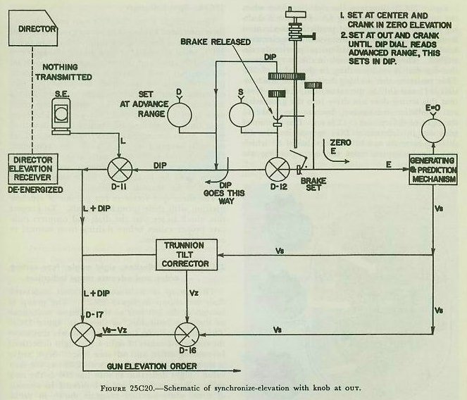
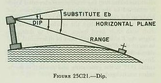
Since the computation of gun elevation order is based on the angle Eb, a substitute value of Eb must be provided when the director is not used. This substitute value of Eb must closely approximate the value ordinarily supplied by the director. The substitute value of Eb is composed of L from the stable element, plus dip.
As shown in figure 25C2l, dip to the target is the angle between the horizontal and a line of sight to the waterline of a surface target. This should not be confused with dip to the horizon. Dip is a function of range.
The graduations on the dip dial are spaced so that, when the index on the inner dial is under the fixed index and the value of range is at the fixed index, the dip-dial shafting is positioned at the corresponding value of dip. The dial is usually set to R2, because of the convenient location of the R2 counter to the dip dial and knob.
Figure 25C20 illustrates the elevation lines when the director is not furnishing Eb. First the E shafting into the generating and prediction mechanism is set to zero by turning the synchronize-elevation knob in the CENTER position as previously described. Then, with the knob in the OUT position, the dip dial is set according to the value of R2. This positions the shafting between the differentials D-11 and D-12 at the value of dip angle. Note that this setting does not drive into the generating and prediction mechanism, because the brake to the right of differential D-12 is set. L is combined with dip in differential D-1 1 to position the Eb shafting correctly as a substitute value of Eb which very closely approximates the corresponding observed value.
Finally, when it is desired to return to normal, continuous-aim-fire, the synchronize-elevation knob is returned to the IN position. This releases the brake to the right of differential D-12. In this position it is turned to align the synchronize-elevation dials with their fixed index, and in so doing realigns the E shafts on both sides of differential D-12 to make the E the same on both sides. This again allows the correct value of Eb, as measured by the director, minus level (L), to drive through differential D-12 to the generating and prediction mechanism unchanged.
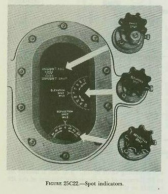
25C18. Spot indicators
Figure 25C22 shows the three spot indicators and their associated knobs. The entire group is located at the right of the indicator unit, as shown in figure 25C1, when viewed by a man facing the indicator unit. Elevation and deflection spots are shown on dials against fixed indexes from minus 180 mils to plus 180 mils. Range spots are shown on two counters. One counter indicates ADD Spots to a maximum of 1,800 yards. The other counter reads DROP spots to a limit of 12,000 yards. The large DROP limit is provided for control of main-battery guns. Spots are received from the director and are normally applied electrically in the computer. However, spot knobs are available for manual settings. For electrical (automatic) reception, the knobs must be locked OUT, while they must be locked IN for manual operation.
The three spot receivers can get out of synchronization with their incoming signals. To prevent this, check to see that the dials and counters indicate proper values before shifting from manual to automatic operation.
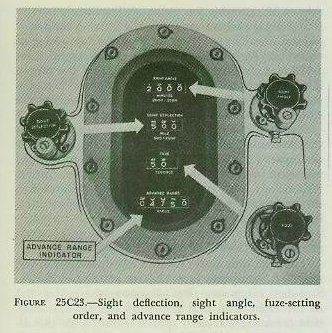
This group of indicators and their associated dials are shown in figure 25C23. The group is located at the left rear of the indicator unit, next to the spot indicators, as shown in figure 25C1. This group includes four sets of counters that show the computed values of sight angle, sight deflection, fuze-setting order, and advance range. Sight angle is shown in minutes of arc, with 2,000 as the zero value. Sight deflection in mils has 500 as the zero value. Fuze-setting order is indicated in seconds of time, while advance range is shown in yards. All but advance range (R2) are normally sent to the guns electrically as computed by the instrument. However, there are three knobs for manual setting of the sight angle, sight deflection, and fuze orders. Manual operation is used with arbitrary values in connection with the control of main-battery guns, and in shore bombardment. Advance range is transmitted only to the star-shell computer. The indicated value of R2 is used with the dip dials, as described in article 25C17, and for checking purposes.
25C20. Other knobs, dials, and switches
Figure 25C1 shows the location and appearance of some of the knobs, dials, and switches mentioned in this article:
1. Initial velocity dial (s) and knob (s). Depending upon the modification of Computer Mark 1A, one or two I.V. knobs and dials are installed to permit setting manually the existing average initial velocity of the battery. The dials are graduated in feet per second between correct I.V. limits for the guns controlled by the computer. For the computer designed to control 5”/38 gun mounts, I.V. settings can be made between 2,350 fs and 2,600 fs. When two dials and knobs are installed, the same setting accounts for I.V. loss due to erosion, variations due to powder temperature, and compensation for air-density variations.
2. Dead-time dial and knob. The dead-time dial shows dead time (Tg), the time in seconds between setting of the fuze and firing of the projectile. The dial is graduated from 0 to 6 seconds, but varies with the average loading interval of the gun crews.
3. Power switch. The power switch energizes all the servo receivers which drive the various quantities into the computer mechanisms.
4. Time push button and director trainer’s rate control key. With the power switch ON, the computer time motor circuit is energized up to a switch called the time motor switch. This latter switch is located inside the computer and is controlled by the time push button and the director trainer’s rate control key as explained below. The time push button is located on top of the computer, to the left of the time dials.
With the power switch ON and the control switch at NORMAL, either closing the director trainer’s rate control key or depressing the time push button starts the time motor. Once the time motor has been started, however, it can be stopped only by depressing the time push button. Thus, in normal operation employing automatic rate control, the computer will start tracking when the director trainer is on target and closes his rate control key. At the end of the tracking run, the computer range operator depresses the time push button to stop the time motor.
With the power switch ON and the control switch at either TEST or LOCAL, the time motor can be started and stopped only by alternately depressing the time push button. Thus, when employing manual rate control or local computer operation, the computer range operator must start and stop computer tracking.
5. Air surface selector switch, sensitivity push button, range time constant knob. Figure 25C1 shows these controls, which were discussed in articles 25C9 and 25C10.
6. Other dials. On the sides of the corrector section are a number of dials used for test purposes. These dials show the following values:
Gun train order (B’gr).
Gun elevation order (E’g).
Unit train parallax (Ph).
Unit elevation parallax (Pv), (for aircraft carriers only).
Level (L).
Crosslevel (Zd).
Elevation trunnion-tilt correction (Vz).
Deck deflection (Dd).
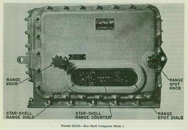
The Star-Shell Computer Mark 1 Mod 0 is designed to control dual-purpose guns for star-shell fire. The star-shell computer will control the illumination of a target which has been detected and for which gun orders are being computed by the Computer Mark 1A. Whereas the Computer Mark 1A computes gun orders to hit a given target, the star-shell computer utilizes those gun orders to calculate another set of gun orders to illuminate that same target. The instrument is mounted integrally with the main computer on the indicator section as shown in figure 25C2. Its appearance is shown in figure 25C24.
25C22. Star-shell computer, functions
The star-shell computer’s functions are to compute and transmit the following for control of the guns firing star shells.
1. B’grjn-Star-shell gun train order.
2. E’gjn-Star-shell gun elevation order.
3. Fn-Star-shell fuze-setting order.
By positioning the proper switches at the fire control switchboard, these outputs are transmitted to the guns firing star shells over the regular circuits used for gun train, gun elevation, and fuze-setting orders from Computer Mark 1A. They are derived from the following inputs:
Mechanical from the Computer
1. B’gr-Gun train order.
2. E’g-Gun elevation order.
3. R2-Advance range.
4. WrD+KRdBs-Star-shell deflection rate.
Electrical from the Star-Shell Spot Transmitter in the Director
5. B’jn-Star-shell deflection spot.
6. E’jn-Star-shell elevation spot.
7. Rjn-Star-shell range spot.
Manual
8. Rjn-Star-shell range spot.
9. R2n-Star-shell range.
Star-shell deflection rate (WrD+KRdBs) is used to correct B’gr (from Computer Mark lA) for motion of the star due to wind and relative target motion such that, at half the burning life of the star (about 30 seconds), the point of illuminations is in the vertical plane containing the line of sight and behind the target. Star-shell fuze (Fn) and gun elevation (E’gjn) orders will cause the star to form 1,500 feet above and 1,000 yards beyond the target. Thus E’gjn must include a correction to compensate for the fall of the star between the time the projectile bursts and the star is formed.
Star-shell range spots (Rjn) are used to alter both the elevation and the fuze orders. Star-shell deflection spots (B’jn) and star-shell elevation spot (E’jn) are used to correct the train and elevation orders respectively. All spots normally are transmitted to the star-shell computer by the star-shell spot transmitter in the director.
25C23. Star-shell computer, operation
The dials and knobs used in the operation of the star-shell computer are shown in figure 25C24. Star-shell range spot (Rjn) is sent to the center dial in the right-hand dial group by synchro transmission from the star-shell spot transmitter in the director. The only marking on the center dial is the white pointer shown in the figure. The ring dial is graduated to read spots applied to the instrument against the fixed index shown in the figure, and is rotated by the range spot knob. To introduce Rjn into the computing mechanism of the instrument, the operator turns the range spot knob to place the index on the ring dial opposite the pointer on the center dial.
Star-shell range (R2n), which is the horizontal advance range measured to the point of the star-shell burst, is displayed on the counter between the two dial groups to enable the operator to read the correct value of R2n required as the input to the left-hand dial group.
The dial group to the left of the instrument (labeled star-shell range dials) consists of an inner dial and a ring dial, both of which indicate star-shell range (R2n) against the fixed index. The inner dial is the fuze dial, and is graduated to compute Fn as a function of R2n. By pushing the range knob to its IN position and setting the value of R2n against the fixed index, star-shell fuze order is set into the instrument. The ring dial supplies inputs to the instrument required in the computation of star-shell gun train and elevation orders. To enter the correct input into the instrument, the range knob is pulled to its OUT position and turned to make the ring dial read the correct value of R2n against the fixed index.
In order to operate the star-shell computer, Computer Mark IA must set up for control of surface fire against the target to be illuminated by the star-shell fire. The main computer can be used to control the guns firing service projectiles against the same target. However, if spots are introduced for the service projectiles, they must be neutralized by opposite spots at the star-shell spot transmitter, since the star-shell gun orders are based upon the Computer Mark lA gun orders.
25C24. Personnel
The full operating crew for the computer consists of a range operator, a bearing operator an elevation operator, a synchronize-elevation operator, and a star-shell computer operator. In addition, a stable element operator and a switchboard operator are required for each computer-stable element combination. The synchronize-elevation operator and the star-shell computer operator usually double as the sight setter’s talker and fuze setter’s talker to the guns, since they can readily read the dials on the computer indicator section. When manual follow-up of the stable element is required, usually one of the latter two operators assists in this operation.
The computer crew on ships with one computer- stable element combination to a plotting room is under the immediate direction of the plotting-room officer, who does not usually function as an operator. In plotting rooms containing two systems, each computer crew usually is supervised by a junior officer in charge of one computer-stable element combination.