| GENE SLOVER'S US NAVY PAGES NAVAL ORDNANCE 1937 CHAPTER XIII PROJECTILES |
| HOME INDEX CHAPTER XIII Projectiles Early Development Length Form of Forward End Form of After End Form of Body Exterior Finish Weight The Bourrelet The Rotating Band Stability and Flight Under-Water Attack Types of Projectiles The Armor Piercing Projectile Manufacture of Armor Piercing Projectiles Penetration Action of the Cap Form of Ogive Common and Thin-Walled Projectiles Shrapnel Illuminating Projectiles Chemical Projectiles Target Projectiles Proof Shot Line-Carrying Projectiles |
 |
| 1307. Weight.-Within reasonable limits projectiles can be given various weights for a given gun. The relation between weight of projectile and powder charge, muzzle velocity and pressure is a part of interior ballistics. The weight of all U. S. Naval projectiles follows a definite system of apportionment, which, stated in calibers, is as follows: |
 |
 |
| where w = approximate weight of projectile in pounds. d = caliber of gun in inches. The weight of projectile per square inch of bore is called the sectional density of the projectile and is represented by the following expression: |
| where S. D. = sectional density. w weight of projectile in pounds. A = area of bore, including grooves, in sq. in. This figure has frequent application in gun and projectile design. The sectional density varies from 0.635 for a 1-pounder up to 10.44 for a 16-inch, averaging approximately 0.6 of the caliber. The distribution of the weight in a projectile is a matter of considerable importance. As a general rule, the center of gravity should be in the longitudinal axis and close to or abaft the center of form. Slight variations in the location of the center of gravity, with respect to the center of form, have negligible effect on the dispersion. For instance, the center of gravity of an 8-inch projectile was moved back and forth 0.5 inch, in a series of firings, without showing any appreciable effect on the dispersion, and, similarly, the center of gravity of a series of 12-inch projectiles was moved to one side of the longitudinal axis, 0.013 inch, 0.039 inch, and 0.052 inch, respectively, without producing appreciable effect in the range or dispersion. 1308. The bourrelet (Plates I and II) is, as previously stated, the forward bearing of all projectiles while the after bearing is sometimes a bourrelet and in other cases only the rotating band is used for this purpose. The shell’s greatest diameter, neglecting the copper rotating band, is that of the bourrelet. This dimension is extremely important. The diameter of the bourrelet or bourrelets of every projectile is measured with ring calipers to guard against the possibility of an oversize in this dimension. The bearing surface of the bourrelet is generally about one-sixth caliber in width, that is, longitudinally with the projectile; and this surface is ground to a fine finish in order to reduce friction and wear of the lands of the gun. Some few small projectiles have no real bourrelet, the entire body of the projectile forward of the band replacing it. CHAPTER XIII, PLATE 1: SEE THE FOLLOWING, FIG.1, FIG. 2, FIG. 3, FIG. 4, FIG. 5, AND FIG. 6. |
 |
 |
 |
 |
 |
 |
| The bore of a gun becomes coppered after repeated firing, with a fine deposit of copper from the projectiles’ rotating bands. Frequently, also, the liner in a gun becomes slightly ridged, after repeated firing, particularly in wake of internal shoulders. A certain clearance must, therefore, be provided between the bourrelet and the lands. The standard U. S. Navy practice is as follows: (a) Up to and including 6-inch caliber, the bourrelet diameter is made 0.015 inch smaller than the bore and a minus manufacturing tolerance of 0.005 inch is allowed so the average radial clearance is 0.00875 inch. (b) 8-inch caliber and above, the bourrelet diameter is made 0.023 inch smaller than the bore and a minus manufacturing tolerance of 0.007 inch is permitted so the average radial clearance is 0.01325 inch. Failure to insure this minimum clearance might result in such a great “pressure of forcing” as would disrupt the gun. Clearances of 0.05 inch have practically no effect on dispersion, but it is reasonable to assume that unnecessary clearance can, at least, have no beneficial effect, and may have an injurious effect on the lands, due to the blows of possible wabbling. It is apparent, also, that the less the clearance, the more accurate will be the initial direction of the trajectory. 1309. The rotating band has three specific functions-to seal the bore, to steady and center the rear end of the projectile for projectiles not fitted with after bourrelet, and to rotate the projectile. It is also utilized to prevent over-ramming in worn guns and to hold the projectile in place during loading and elevating for firing. In addition to these functions, the band has considerable effect on the range, dispersion, muzzle velocity, and life of the gun. Note: Rotating bands are also called forcing bands. Until 1921 rotating bands were made of commercially pure copper for all minor and medium caliber projectiles, and of cupronickel alloy containing 2.5 per cent nickel for major-caliber projectiles, the nickel being added to secure greater strength. In 1921 the practice of using commercially pure copper for all rotating bands was adopted. As a general rule rotating bands are about 1/3 caliber in width. In some instances, particularly abroad, the width of a band is kept down to a maximum of about 1.5 to 2.0 inches, and where a greater strength is necessary two separate bands, separated by a short distance, are provided. This system has considerable merit. |
 |
 |
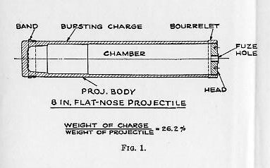
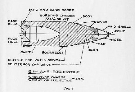
 |
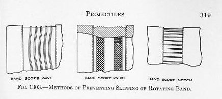
| The band is secured in a score cut in the projectile body, there being a dovetail on each edge to assist in overcoming centrifugal force, and either waved ridges, longitudinal nicks, or knurling in the bottom of the score to insure against slipping during acceleration. The band is made as a ring of slightly greater internal diameter than that of the body and is slipped over the score while hot, and pressed radially into place in a powerful hydraulic press called a “banding press.” |
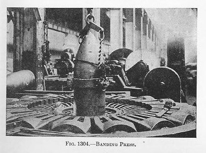
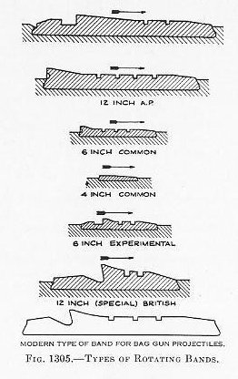
| Figure 1304 shows a banding press consisting of a large number of hydraulic rams arranged radially. Each ram is fitted with a short segment of a circle for exerting pressure against the rotating band to cause the copper to flow into the securing dovetails, ridges, nicks, or knurling. The projectile with its loose rotating band is lowered, base down, into the banding press. The rotating band is then secured by having all hydraulic rams simultaneously exert pressure upon the rotating band. The length of the segments can be varied to suit the circumference of the projectiles of various calibers. 1310. The forward edge of the band is slightly conical and fits into a corresponding coned seat at the origin of rifling. The central portion of the band is generally cylindrical and of a slightly greater diameter than the diameter of the bore including grooves. An expression often used to obtain the diameter is D = C+2p +.02 where C is the caliber of the gun, and p the depth of the grooves. It will be observed (Fig. 1305) that on the rear part of practically all bands is a raised lip. This lip serves the purpose of insuring a good gas seal and at the same time, because of its considerably greater diameter, preventing over-ramming in a worn or eroded gun |
 |
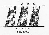
| When the gun is fired and the pressure rises, the projectile is forced into the rifling which then engraves the band to fit the contour of the bore, and the revolution of the projectile ensues. It is easily seen that the driving face of the lands should be radial so that the rotative force will be applied normally. 1311. With uniform twist rifling the lands in the bore present a constant angle to the band. After the first engraving, therefore, there is no further flow of the metal in the bands other than the slight drag and wear due to friction. With parabolic or increasing twist rifling, however, the lands in the bore present a constantly increasing angle to the band. In this case, therefore, there is a continual flow of metal, due to the changing pitch of the thread. This condition is shown in Fig. 1306, which diagrammatically represents the parts of an engraved band covering three grooves in the rifling. |
| The shaded portions represent the imprint of the land on the band when the projectile leaves the muzzle, AD being the initial driving edge with the smaller twist and AF being the final driving edge with the larger twist. During the travel of the projectile down the bore the imprint of the land has been shifted from ABCD to ABEF. It is evident, therefore, that the copper under A DF has been removed during the travel and that the projection on the band which remains in the groove of the gun is covered by BGHC. 1312. In order to insure a tight joint, especially in eroded guns, the diameter of the cylindrical portion of the band is generally a few thousandths of an inch greater than the diameter of the bore across the grooves. It is clearly evident, however, that any excess metal in the band will be pressed or wiped back toward the base of the projectile, this being more pronounced in wake of the lands. Should this excess metal be of sufficient quantity it will form a scalloped skirt extending abaft the band score. Now at the instant that this skirt clears the muzzle there will be a rush of gas past it, which, aided possibly by centrifugal force, may turn this skirt out radially at a considerable angle. This is called fringing and a pronounced fringe can have a material effect on the range and dispersion, the effect being greatest on minor and medium caliber projectiles. The successful design must not only provide sufficient metal in the band to secure the desired performance, but must also insure against fringing. Grooves or “cannelures” are placed in the middle portion of large bands, for the purpose of allowing space for this excess copper and a large groove is also frequently provided abaft the lip to take this excess copper. 1313. It is important to locate correctly, on all projectiles, the fore-and-aft position of rotating bands relative to the base of the projectile. This is especially true in the case of projectiles not fitted with a front bourrelet. The resultant of initial pressure on the base of the projectile is seldom axial with the bore; it is usually inclined to this axis, and does not pass through the center of the base. This eccentric and oblique action of the resultant gives rise to a couple, which tends to rotate the projectile about one of the diameters of the rotating band, and to produce jolting or beating along the walls of the gun (“balottement”); the projectile leaves the piece with perturbations, which do not allow an efficient overcoming of the air resistance, and which produce a sensible diminution of range and accuracy of fire. Experiments have shown that there is one particular position of the band in which this couple, to which the projectile owes its perturbations, is reduced to a minimum, and to which, as a part of other conditions, the maximum range and best stability of flight correspond. In this position the rear edge of the band is one inch from the base of the projectile. However, this advantageous positioning of the rotating band cannot always be attained. 1314. Stability and flight. The mathematical demonstration of the stability of projectiles is not only without the scope of this work, but is by no means in a settled condition. The difficulty lies in our inability to determine the precise nature of the forces acting on the projectile in flight. The gyroscopic effect of the rotation of the projectile is to stabilize or hold its axis in a fixed position in space. Were this action to remain unaffected by external force, the projectile would travel with its axis always at the same angle with the horizontal. Experiments have shown, however, that the axis of a projectile having a smooth flight is practically in the trajectory at the point of fall, and presumably, therefore, throughout its entire flight. The effect of atmospheric resistance is, therefore, not only to slow down its rotation and translation, but to form with the gyroscopic force, a couple which effects a continual tipping down of the forward end of its longitudinal axis. It is quite evident, therefore, that there must be a specific rotational speed most suited, for a given projectile, to a particular velocity. The balance of this couple is an important feature in any discussion of rotation. If, in the resultant of the couple, the atmospheric resistance preponderates, the projectile ceases to be stable and tumbles. If the gyroscopic force preponderates the projectile refuses to tip and a complex series of forces immediately ensues which causes the projectile to corkscrew. The balance is not restricted to a precise relation, but allows certain limits between which the flight is smooth and stable. 1315. A study of the plotted trajectory of any projectile will show that its curvature is small during the early stages and final stages but is large during the middle stage, the maximum curvature being in the immediate vicinity of the vertex. That is to say, therefore, that the yielding or tipping of the axis must accomplish a much greater and more rapid change in direction while in the neighborhood of the vertex than in any other portion of the trajectory. It is generally accepted that the atmosphere has a greater retarding effect on the translational velocity, than on the rotational velocity. This being true, the ratio between translational energy and rotational energy continually decreases during flight ; or, in other words, the gyroscopic force continually increases in relative proportion ; or again, a projectile which starts with a minimum margin of rotation gradually increases that margin. It might be mentioned parenthetically that experiments have been recently undertaken, principally abroad, to put vanes on the ogive which will increase the rotational retardation and tend, therefore, to preserve the initial ratio between the rotational and translational velocities. Now, from the above it is evident that the performance of the projectile at the vertex is the essential feature of a study of its rotation. It should be noted that with low angles of elevation, or flat trajectories, the curvature at the vertex is so slight as to require no special consideration, but as the elevation increases the curvature becomes greater until at angles of elevation of about 60 degrees or greater the curvature at the vertex is abrupt, and at such angles a projectile will not dip sufficiently, but may either tumble or descend base first. We may now consider the phenomena which enable us to fix the proper rotation to give a certain projectile. 1316. If a projectile is launched with insufficient rotation, the gyroscopic force is overcome by the resultant of the external forces and the projectile “tumbles” or goes end over end. This is discernible through pronounced and intermittent sound developed during early flight and through excessive dispersion. It is also determined by firing the projectile through cardboard screens. In service such phenomena are exhibited in old guns with such badly eroded bores that the rifling is unable to impart the designed rotation to the projectile. Projectiles with insufficient rotation have been known to turn sideways within 100 feet of the gun. If a projectile is launched with excessive rotation, there is little early indication of difficulty, other than excessive drift, and little effect on short ranges with flat trajectories. As the elevation is increased, however, and vertices are reached which require rapid change in inclination or dipping, the gyroscopic forces preponderate, a corkscrew path results, and the visible effect is excessive dispersion. Insufficient rotation is connected with short range phenomena, while excessive rotation is connected with long range phenomena. 1317. Under-water attack.- When an ogival-headed projectile, traveling in air, strikes water, it deviates from its trajectory in a violent and uncertain manner. At small angles of fall it tips up, runs parallel with the surface for a short distance and then, if it still has sufficient velocity, emerges and again takes to the air. This is called a ricochet. Practically all shells ricochet to the right of the line of fire. At large angles of fall, it is liable to deviate in any irregular direction or sink. The desirability of the attack of submarines by gun fire from surface or aircraft has resulted in the development of projectiles which maintain their trajectory, upon entering water, with reasonable accuracy. In these projectiles the ogival form is abandoned and a square head is substituted. Such projectiles are called, in our Navy, “flat nose” projectiles and elsewhere are called “diving shell.” (Plate I, Figs. 1 and 2.) The retardation of the translational velocity of these projectiles in both air and water is excessive, but such a sacrifice has to be made in order to secure accuracy upon and after water impact. Interesting proposals have been made to fit flat-nose projectiles with thin wind shields or false ogives which will collapse and be wrenched adrift upon impact with water, thereby preserving both good flight in the air and under-water accuracy. Section II. Types of Projectiles. 1318. The impact damage which a projectile itself does is entirely secondary to that which results from its burst. The design of most naval projectiles is based primarily on using the projectile as a vehicle with which to carry a quantity of explosive into a ship and secondarily to provide missiles with which to carry the force of the explosion. Where the projectile must meet heavy face-hardened armor, the result is a massive piece of steel with a heavy head, thick walls and a small cavity, called an armor piercing projectile. In such projectiles the weight of the bursting charge (high explosive) varies between 2.1 per cent to 2.6 per cent of the total weight of the projectile. If the size of the charge is increased the Projectile is unequal to matching even caliber plate at battle ranges and angles of fall, while if the size of the charge is reduced the fragmentation of the projectile on burst is not efficient. (Plate I, Fig. 3.) Where the projectile may encounter armor of a thickness of only to 1/2 caliber, or a combination of light side plating, bulkheads, and decks, the cavity can be somewhat enlarged, and the design is called a common projectile. In such projectiles the charge represents, for major and intermediate calibers, about 6.0 per cent of the total weight, and for sizes below 6 inches the percentage falls to about 3.0 per cent to 3.5 per cent. (Plate I, Fig. 4.) Finally where the steel envelope is made only sufficiently strong to stand the shock of firing in the gun, the cavity is as large as possible. This design is generally spoken of by ordnance engineers as a high capacity projectile, but in the American Navy individual types of projectiles falling under this general class are given individual names based primarily on their use or design (Plate I, Figs. 2, 5, and 6). As a class, however, they may be spoken of as thin-walled projectiles. Such projectiles are fitted to burst by action of either impact or time fuzes. It should be noted that the strength of the walls of such projectiles is fixed by the setback; in consequence, the lower the muzzle velocity of the gun, the greater will be the relative size of the cavity, for a given weight of projectile. In high velocity (3,000 f. s.) ogival-headed projectiles, the weight of charge can be as high as 10 per cent to 12 per cent of the total projectile weight and in low velocity (1,000 f. s.) flat-nose projectiles, this charge can be increased to as high as 25 per cent of the total weight of the projectile. . It is thus seen that service projectiles are broadly classified as armor-piercing, common, and high capacity. In addition to these three general classes, there are other projectiles which do not fall under any of these classes. These projectiles are designed primarily for use in time of peace and are as follows: “Target”--------------designed solely for target practice and proving ground work, as an economical substitute for the A. P. projectile. “Proof Shot”---------designed primarily for proving ground work and for spotting practices. “Line Carrying”-----designed to carry a line for use in rescue work. THE ARMOR-PIERCING PROJECTILE. 1319. Development.—The predominating school of thought during the Civil War, in connection with the attack of armor, was to smash in the armored side of a vessel with solid shot and spread splinters from the broken projectile, plate and backing, over the back areas, rather than to penetrate the armor and burst the projectile in the rear. As previously noted, this theory had a short life and the introduction of rifling finished it. It was a long time, however, before the use of the solid shot was abandoned. As late as about 1895 solid shot were made for armor penetration only. There are, however, frequent revivals of variations of the “smashing effect.” The development of high explosives led to the advancement of the theory that a large quantity exploded against the armored side of a vessel would cave in the armor and plating and completely destroy that part of the vessel in the general neighborhood of the impact. Costly and elaborate experiments have conclusively shown that high-capacity, high-explosive projectiles detonating on the armored side of a vessel have no appreciable effect on the armor and negligible effect on the adjacent ship’s structure. Furthermore, the engagements of the World War show beyond doubt that, while major-caliber bombardment or common projectiles may produce great havoc in upper works and unarmored localities, modern armored vessels are almost immune to disablement by other than armor-piercing projectiles of the finest quality. The first development in armor piercers, after the ordinary cast iron shot, was the Palliser chilled-iron projectile, which was introduced in England in 1866. This projectile was an iron casting, cast point down, the lower part of the mold being an iron chill while the upper part was sand. These and similar projectiles were used until about the introduction of steel armor. It is quite probable that cheapness was an important factor in their continued use, for in 1862 Whitworth patented a case-hardened heat-treated mild-steel projectile with a hard head and soft base. Wrought iron was frequently tried, but, due to its inherent ductility, never made any headway. In 1878 extensive trials at Shoeburyness showed that the Whitworth projectile had surpassed all other makes in penetrative qualities. But, about this time the firm of Jacob Holtzer et Cie., in France, produced a forged high-carbon, nickel-chrome, crucible steel armor piercer which, in spite of the efforts of rival manufacturers to duplicate, remained the most efficient projectile in existence for many years. In 1886 the Navy Department secured a few Holtzer projectiles. These contained about 1.80 per cent chrome and .80 per cent carbon. Shortly after this the Holtzer and rival processes were imported into America. The next real development in armor piercers was the introduction of the cap. In 1878 a comparative test was made in Europe of the effects of projectiles against the face and back of a compound plate. The same projectile which smashed on the face completely penetrated when the plate was reversed. A thin wrought-iron plate was then placed in front of the hard face and this was found to materially increase penetration. And finally a wrought-iron jacket was placed over the point of the shot which gave the same result of increased penetration. It appears to be authentically established that in 1883 Colonel Inglis of the English Ordnance Committee devised the first soft-steel caps. In 1896 Mr. I. G. Johnson submitted some 6-inch solid fluid-compressed steel shot to the Navy Department, on the noses of which he had placed a small cylindrical mild-steel cap. An important feature of these caps was that an annular space was left between the point of the projectile and the rear portion of the interior surface of the cap, which was filled with graphite. These projectiles completely penetrated a 7-inch Harvey plate when striking at 2,100 f. s., while similar uncapped projectiles at the same striking velocity smashed on the plate. Shortly after this, caps were placed on all American armor piercers, but the graphite feature was later abandoned. A few years ago the cap was improved by making it of high-carbon chrome steel and hardening it decrementally, although the idea had been patented in 1896. Since the introduction of forged high-carbon, nickel-chrome steel and the cap, there have been no radical improvements in armor-piercing projectile manufacture, other than a gradual increase in skill of manufacture. Up until comparatively a few years ago armor piercers were always made from crucible steel, but in the late nineties the use of small open hearths began and now most armor piercers are made from open-hearth and electric steel. 1320. Manufacture of armor-piercing projectiles.—Open-hearth steels—acid, basic, and electric—are used for these projectiles, but the melting is given far greater care than is received by the average commercial steel. The ingots are cast nose down in iron moulds in order to chill them rapidly to prevent piping and injurious segregation. There are two general systems of forging. In one the ingot is cast of greater diameter than the finished projectile, and is forged down, being lengthened in the process, under a press or hammer, and in this process he cavity is bored out. In the other process, the ingot is of smaller diameter than the finished projectile, is upset in a die under a press to he proper diameter, and its base is then pierced by a punch to form he cavity, the rear walls of the body being somewhat extruded. In the first process mentioned the grain or fiber of the steel is longitudinal whereas in the other process it is transverse. The rough forgings are then annealed, after which they are rough machined nearly to size. The next step is a series of heatings and quenchings in oil and hot water for the purpose of refining and fibering the grain structure. After this treatment the forging is turned to exterior and interior dimensions, allowance being made for the fitting of base plug, and finishing of band score and bourrelet. The next step is the hardening, which is accomplished by a graduated heating beginning at the point followed by a complete quench in agitated cold water. This puts the entire projectile in an exceedingly hard condition. The heating for this treatment is generally accomplished in a bath of molten lead, such procedure being conducive to accurate control of both temperature and position of application of heat. After this the base of the projectile is heated to a lower temperature than was used for quenching and upon withdrawal from the bath or furnace is suspended nose down and immersed up to the bourrelet in agitated cold water. This procedure draws or tempers the rear portion while preserving the hardness in the head. The result is an exceedingly hard head to the rear of which the hardness gradually decreases with increase in toughness. The hard head is to effect the smashing of the plate’s face while the tough rear is to support the head and stand the breaking strain of angle impact. (See Plate III.) |
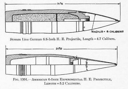
| Section 1.-General. 1301. Early development.-All projectiles intended for use in cannon at long range are similar in shape, irrespective of their size and the purpose for which they are intended. The shape now in current use is the result of an evolution which dates back to the first part of the Fourteenth Century, when cannon are first known to have been in existence in Europe. From that time until 1520 the principal projectiles were solid spherical stone balls and iron-headed darts. It is really astonishing to realize that guns of 25-inch caliber, firing a stone ball weighing about 700 pounds, were made as far back as about 1382! While the casting of iron was known in the Fourteenth Century it required many years and experiments to apply the art to projectile manufacture. With solid spherical projectiles the sectional density can only be varied by varying the material in the projectile, and it is quite probable that the development of iron projectiles was retarded by the inability of the guns to stand such heavy projectiles without bursting. Gradually, however, it grew into use and in the early half of the Sixteenth Century cast iron became the principal material used in projectile manufacture. Shortly after this the hollow ball, or shell, was introduced. Few developments of importance occurred thereafter until 1854, when the application of rifling to cannon began. That development had an immediate and pronounced effect on projectile design. The rotation of the projectile permitted its elongation, thereby securing increased range by reducing the head resistance for the same mass, increasing the accuracy of flight, increasing its penetrative ability, and increasing the mass of the projectile which a given gun could accommodate, or, in more technical terms, the sectional density of the projectile. 1302. Length.-At first projectiles were but slightly elongated, but each increase in the power of the gun and the efficiency of the rotative mechanism was followed by a corresponding increase in the relative length of the projectile. During the Spanish War our projectiles were between 2.5 and 3.0 calibers long, and during the World War their length had increased until 3.5 calibers was considered a medium length and 4.5 calibers was frequently and successfully used, with a few instances of even longer ones. 1303. Form of forward end.-Early in this development many experiments were conducted to determine the proper shape for the extremities. The form adopted for the front end was that known as the “ogive.” The ogive is one-half of the form generated by the revolution of the arc of a circle about its chord, the chord being the axis of the projectile. The versine of this arc becomes the semi-diameter of the projectile, the sine of the arc being the length of the ogive. The shape of this ogive is generally expressed by stating its radius in terms of caliber. At the present time the majority of U. S. Navy projectiles have ogivals of 7 calibers radius. Frequently the ogival shape is secured by the combination of several arcs of different radii. In recent years, the ogival shape has occasionally been abandoned in favor of a conical shape, or partially conical shape, as that form lends itself with greater facility to mechanical processes. With proper rotation, it is desirable to keep the center of gravity of the projectile to the rear of, or in the immediate vicinity of, the center of form, particularly in long projectiles. As piercing projectiles require a blunt and solid nose for penetrative ability, the amount of metal in the forward end must be great. Also a fine forward form is conducive to long range. To reconcile these two opposing yet necessary qualities it has been advantageous to adopt light nose pieces, wind shields, or false ogives, all of which names are more or less synonymous. Several types of these are shown in the following sketches, and on Plates I and II. The following table shows, for a 6-inch projectile, the effect on the range of varying the radius of the ogive; the muzzle velocity, angle of elevation, weight of the projectile, and form of rear being common for all shots. Radius of ogive in calibers................. Length of projectile in calibers.........................Effective range in yards. 2.5.....................................................3.00.................................................................9,083 5.0.....................................................3.37.................................................................10,549 6.0.....................................................3.50.................................................................10,921 7.0.....................................................3.62.................................................................11,285 The percentage of increased range, of the finer form over the blunter form, increases with the angle of elevation; that is to say, the improvement becomes greater as the range increases. 1304. Form of after end.-Variations in the shape of the rear end of the projectile have not been as prolific of beneficial results as might be expected from the preceding discussion of the forward end. All projectiles have the corner of the base turned to a small radius and for many years that shape was standard. Practically all U. S. Naval projectiles have this rounded corner, the radius varying from .375-inch for large projectiles down to a mere touch of the file on the corner of the small ones. Frequent firings have, however, shown that increases in range can be secured by shaping the base to a finer form than a mere rounding of the corner. This scheme is generally referred to by naval ordnance engineers as boat-tailing, an expressive but peculiar term. But the deterrent fact is, that while comparatively small increases in range may be secured, they are generally accompanied by loss of accuracy! This is generally assumed to be caused by a flip or unequal side slap given to the rear of the projectile by the powder gases as they escape through the annular opening around its base before it has entirely cleared the muzzle. |
 |
| It has finally been determined, however, that a high velocity (2,500 to 3,000 f. s.) projectile will give slight increase in range without loss of accuracy if the rear end is coned between 5° and 8° for a distance of from approximately 0.25 to 0.75 calibers, the angle of the cone between those limits depending on the velocity and form of ogive. In cartridge-case projectiles another factor is added in connection with the form of the after end, for in such projectiles that portion must be kept cylindrical for a considerable length in order to provide a proper bearing for the cartridge case. 1305. Form of body.-Between the ends, whatever their shape and length, is the cylindrical portion or body of the projectile. At the after end of the body is the rotating band or bands, and at the forward end is the bourrelet. In late projectile design, the tendency has been to use both a front bourrelet and a rear bourrelet or bourrelets. The rear bourrelet is either aft of or immediately forward of the rotating band. Between the bourrelet and the rotating band (or between the front and the rear bourrelets) the diameter of the body of the projectile is slightly reduced, in order to provide a generous clearance from the bore of the gun. It is the support and bearing provided by the band and bourrelet or by the two bourrelets which steady the projectile in its travel through the gun and it is quite evident, therefore, that there must be a reasonable distance between them; else too heavy a duty will be demanded of them in preventing wabbling. There is no fixed rule as to what this distance must be, but designers generally allow about one caliber for minor-caliber projectiles and increase the distance gradually up to about 1.4 calibers in major-caliber projectiles. We have touched on the benefits of streamlining the forward and after ends, and also on the limitations on lengthening the projectile as a whole. Considering these points in connection with the distance between the band and bourrelet or between the two bourrelets, we can at once appreciate the reason why projectile design is a compromise, and why advantage cannot be taken to the utmost of promising individual features. 1306. Exterior finish.-As a general rule projectiles are given, except on the bourrelet, only a rough machine finish; that is, one which, while smooth to the eye from a distance of say eight or ten feet, shows on closer inspection the marks of the turning tools. It is a popular fallacy that a smooth finish is conducive to accuracy. A very complete experimental firing was carried out some years ago in which a series of 14-inch target and armor-piercing projectiles were fired at a standard elevation, velocity, and projectile weight, half of the projectiles being carefully ground and polished to a fine finish, while the other half were left with the usual finish. The difference in finish appeared to have negligible effect on the dispersion; in fact, those projectiles with the rough or service finish gave a smaller dispersion than did those with the polish! |
 |
| Finally, the projectile is sand blasted, the band score is finished, and the band pressed into place, the cap and wind shield are put on, the bourrelet is ground, the band is turned to size, and the base plug fitted. The cap follows, in general, the same methods of manufacture and treatment as are applied to the projectile, although, of course, no special ingot is made for it. After forging it is annealed, rough turned, fibered, then finish machined, except threading for the wind shield, then decrementally hardened, and finally finish turned, threaded, and installed. Caps are made of the same kind of steel as are the projectile bodies, except that the carbon, nickel, and chromium are not so high. Caps are secured to the projectile by several methods. The one most commonly used consists of peening the skirt of the cap into notches cut into the ogive of the projectile. Figure 1304, showing an armor piercer in the banding press, also shows the notches in the ogive. Another method consists of soldering the cap to the ogive with a special low melting point solder. Such a solder is required to prevent the heat necessary for soldering from drawing the temper of the ogive. Caps should be held securely in place, and it is quite probable that their efficiency on oblique impact is materially affected by the security of the bond. The notches in the ogive are certainly no source of strength. The use of solder is therefore looked upon with favor by many ordnance engineers. It occasionally happens that caps become loosened by rough handling. Such projectiles should be returned to an ammunition depot for recapping. A loose cap is a source of grave danger. If the cap should come off after being loaded in the gun, the projectile might ride over the cap. This would, in effect, increase the diameter of the projectile, and the gun might be disrupted by the pressure that would build up behind the projectile as a result of the increase of resistance. The wind shield is made of either cast iron or forged mild steel and has no special strength other than that necessary to prevent destruction during handling and setback. Wind shields are generally screwed on the cap, and frequently the thread is cut on a tapered surface. After screwing home, they are “set” by a center punch at the joint. They sometimes become loose in handling and in that event they should be tightened and reset. Base plugs are of good quality nickel steel. The only special requirement is that their longitudinal axis should be normal to the longitudinal axis of the original ingot, a precaution taken to insure the maximum strength against shear or collapse under the chamber pressure of the gun, and to prevent piping or porosity from leading flame or gases into the bursting charge. This latter precaution is taken with all projectile base plugs and will not be referred to again under other projectiles. The steel for A. P. projectiles is the finest quality, nickel-chrome steel. Due to the comparatively small mass and more convenient size the carbon can be carried much higher than is possible in armor manufacture. For instance, we find the carbon content as high as 0.75 per cent. Similarly, the chromium can be carried a little higher and we find the chromium content as high as 2.60 per cent. The nickel runs about the same as for armor. 1321. Penetration.- . Calculations as to penetration are all based on the deMarre formula, which was discussed under Armor, although with less reliability than in the case of armor. A projectile may penetrate or “defeat” a plate but break up in the process, to such an extent as to prevent it from bursting effectively. In considering penetration from the projectile standpoint, the standard of performance must be effective bursting condition after penetration. Effective bursting condition is generally taken as complete integrity of the cavity. Thus the projectile may lose its nose, or even a large portion of the head down to about the bourrelet, but it is considered to be effective if the cavity is not exposed by cracks or fractures. When a projectile strikes a plate normally, penetrates without deformation, and stops just after its bourrelet has completely passed through the plate and all ragged edges, it has delivered to the plate all its energy, except for the heat generated in the projectile, which is comparatively slight. Now, it is generally accepted that such a condition represents the maximum delivery of kinetic energy which a projectile can accomplish. At higher velocities it is probable that the plate requires less energy to accomplish its defeat. No demonstration of the accuracy of this theory can be made as no satisfactory device has been developed with which to measure residual velocities, but it is founded on considerable observation. Such a theory being correct, it follows that, for normal impact and complete penetration of the plate, the higher the striking velocity the less the strain on the projectile. Now, when the angle of obliquity is between normal impact and the maximum obliquity at which the projectile will bite into the plate, very different conditions are imposed. The primary phenomenon is that the projectile generally tends to readjust its axis toward the normal, or, in other words, strives to seek normal penetration. This action, of course, introduces violent side strains, and when projectiles break on angle impact they clearly show this side strain by breaking across the body. The fact that rotation still persists must be remembered. Now it is clearly evident that in oblique impacts, the greater the velocity the greater must be the side or twisting strain. To reduce the combination of the two conditions mentioned above to mathematical terms has so far proved impossible. In comparing projectiles, therefore, their relative efficiency can only be determined by confining the comparison to certain arbitrarily fixed conditions. For instance, we may fix a specific angle of obliquity and vary the velocity to effect comparison, or we may fix the velocity and vary the angle of obliquity to effect comparison. Or, on the other hand we can fix the velocity and obliquity and vary the plate thickness required. 1322. The action of the cap. Various theories have been advanced as to the reason for the increase in penetration secured by the application of the cap. The simplest, and perhaps the most reasonable, is that the cap acts to break down the initial strength of the plate, allowing the nose to reach an already strained surface, and then provides powerful circumferential support to the point and nose as they begin to penetrate the hard face, maintaining the support until they are well into the plate. This theory has been supported by observations of many experiments. Finally the cap has the effect of increasing the biting angle; that is to say, a capped projectile will “bite” or fail to glance off at greater angles of obliquity than will the same projectile without a cap. This is due to the greater bluntness of the front end of the cap. 1323. The shape of the ogive of the projectile itself has considerable effect on the efficiency of the projectile. The curvature of the ogive was increased to about 2.5 calibers because of the desire to reduce air resistance and this curvature was retained under the cap after its adoption. The introduction of the wind shield has obviated the necessity of having a long nose to reduce air resistance on projectiles. If the projectile has too sharp a point, the nose will probably be broken off on impact, while if too blunt, the projectile will have poor penetrative qualities. Present practice is to fix the radius of the ogival of armor-piercing projectiles at approximately two calibers. COMMON AND THIN-WALLED PROJECTILES. 1324. The development of the common and thin-walled projectiles followed logical channels, being based on the attack upon unarmored vessels, the upper works of armored vessels, earthworks, fortifications, and aircraft. As a general rule the design and selection of materials of these projectiles is predicated, so far as is consistent with efficient operation, on cheapness and quantity production. In fact, the coordination between design and quantity production is of almost vital importance. These considerations led to the selection of plain 0.45 per cent to 0.60 per cent carbon basic open-hearth steel, and the adoption of a design which reduces the number of forging and machining operations to a minimum. In designs requiring the maximum attainable weight of bursting charge or calling for peculiar interior arrangements, greater strength per unit of area will probably be required, in which case a higher carbon or even a nickel-steel may be necessary. Methods of fabrication differ with the caliber and type. In large calibers each projectile is made from a separate ingot, while in medium calibers large ingots are “cogged down” in a rolling mill to billets of round, square, or polygonal section and then cut or broken to proper length. The ends of these blanks are usually inspected to eliminate those which contain piping or injurious segregation. Considering major and medium caliber projectiles, and the ingots or billets made for them, as mentioned above, fabrication continues, in general, as follows (Fig. 1307): The projectile blank is heated, placed nose down in a die approximating the exterior contour, but of excess diameter, and then pressed under the plunger of a hydraulic press, thus forming the ogive. A piercing die or plunger of slightly less diameter than the cavity is then forced into it, which forms the cavity. These two steps can be done with one heating. |
 |
 |
| In some projectiles this is the only forging required, but generally the extrusion performed by the piercing die is insufficient to make the cavity long enough. In this case, which is quite general, the forging or blank is reheated, and placed in a draw-bench, the nose being placed in a die containing a circular hole slightly larger than the finished diameter, and it is then forced through this drawing die by a hydraulically operated plunger which is inserted in the already partially formed cavity. This drawing process forces the sides back over the plunger, thus extending the blank to the required length. In some cases more than one draw is required, and this is generally performed in one heat by forcing the forging through several rings or dies in succession in the same draw-bench. The method just described applies, of course, to open-base projectiles. Where the base is to be solid and the nose is to be open the same general process is followed, except that the projectile is worked from the nose instead of from the base. The blank is then generally annealed, or normalized, and if high physical properties are required, it may be heat-treated to secure them. It is then passed to the machine shop for finishing. The finishing consists in turning and boring to the correct dimensions and tolerances, banding, fitting the plug, painting the interior of the cavity, and inspecting and stamping for shipment. As a general rule all surfaces are finish machined except as noted below. Many efforts have been made to omit the machining of the cavity but the forge finish is not satisfactory because the forging temperature is so high that a rough and scaly surface results. Some projectiles are fitted with heavy nose or base plugs, others have smaller adapters to carry the fuze, and others may be designed to receive the fuze itself. In most of these classes the cavity is always of larger diameter than is the hole for these fittings. This condition is met in two ways. Where the hole is large and the amount of metal to be removed from the rough forged cavity is small, or where the projectile is completely heat-treated, the interior is finished in a boring machine or lathe, using a tool on the end of a bar which is inserted in the hole. This bar is swung on a pivot in order that the tool can be made to follow the desired contour of the interior. Where the cavity is large and entails the removal of considerable metal, or where the forward or after fuze or plug hole is so small as to render machining impracticable, an entirely different process called nosinq-in or basing-in, as the case requires, is employed. Here, prior to closing the nose or base, the inner portion of the cavity is machined to size while the outer portion of the cavity is machined to a cylindrical or nearly cylindrical size, any shoulders or seats being also partially machined. That part of the projectile which is to be closed in is then carefully heated in a non-oxidizing flame, and is then either forced, under hydraulic pressure, into a die which is cut to the proper exterior shape, or is pressed into shape under radial pressure. As was stated above, this process can be applied to either the ogive or the base. Figure 1307 shows the various stages of piercing, drawing, and nosing of a 6-inch army shell. This operation can be so satisfactorily performed that no machine work is necessary on the closed-in portion except the fitting of screw threads and gas-tight seats. It is generally customary to select tensile-test specimens from heats or lots after all forging or heating is completed, in order to insure that uniform and satisfactory results are being secured. The processes referred to above apply to practically all kinds of projectiles, except armor piercers and minor-caliber projectiles. Minor-caliber projectiles are generally machined from round rolled bars, the forging to shape with final finishing being more expensive than complete machining. Base plugs, fuze-hole plugs, adapters, and the miscellaneous interior parts of shrapnel, illuminating projectiles, gas and smoke projectiles, are manufactured by the various drop-forging, drawing, and machining processes covered in textbooks on mechanical processes. |
 |
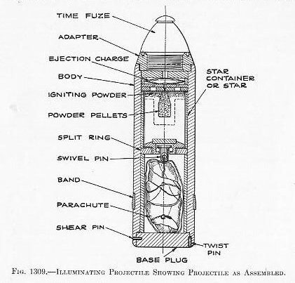
| SPECIAL PROJECTILES. 1325. Shrapnel (Fig. 1308).- This type of projectile is designed for use against personnel and its only naval use is, therefore, in connection with landing parties, bombardment of fortifications, and attack upon aircraft. It is interesting to know that the name is derived from the inventor who brought it out in Europe in 1784. The most common form of shrapnel consists of a case in the rear of which is a black-powder bursting charge, connected to a nose fuze by a central explosion tube around which is packed a large number of lead (88 per cent)-antimony (12 per cent) balls held securely in place by a matrix of hot-poured resin. When the fuze acts the balls are expelled forward by the bursting charge and scatter in a cone-shaped cloud. Shrapnel are, however, frequently given other features. For instance, a high explosive may replace the resin to increase the violence of the burst and the area of damage; or there may be a heavy head with a high-explosive burster and suitable fuze in order to follow the cloud of balls with a secondary explosion, and, finally, the balls may be replaced by small hollow open-ended cylinders in which phosphorus or other incendiary compound is packed. The object of this design is to add, to the local explosion and distribution of missiles, the probability of creating a conflagration. This design is particularly valuable against aircraft of all descriptions, especially those which employ hydrogen. 1326. Illuminating projectiles. In this type we have a case, similar to a shrapnel case, with a very small burster in the front end just abaft the fuze, and an interior assembly of a star or candle with a parachute, and a very lightly held base plug. The explosion of the burster, or, as it should be called, the expelling charge, forces out the base and the interior assembly. It is quite desirable to expel the assembly with considerably velocity, at least 300 to 400 f. S. relative to the case, in order that it will have as small a velocity, in space, as is possible. It would be preferable to have the assembly expelled at the same velocity as the case is traveling, but at present this is not possible. The star or candle is a steel container in which is packed, under heavy pressure, a illuminating compound in which magnesium is an important constituent. The explosion of the expeller ignites the candle or star. The parachute is attached by means of shroud wires to the closed end of the star container and, in addition, the center of the parachute is attached to one end of a release device, the other end of which is attached to the star. The parachute is carefully folded and with the shroud wires and release wire is so rolled that upon expulsion it comes into action to retard and then support the star. The release wire, being intentionally short, holds the center of the parachute near the star so that the parachute spills most of the air with which it comes in contact. The release is so adjusted that when the star has been sufficiently retarded, the release wire is freed so that the parachute fully inflates and supports the star. |
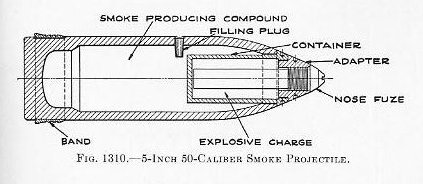
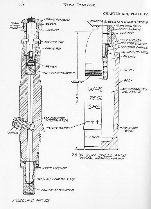
| 1327. Chemical projectiles.-It is not probable that heavy caliber projectiles and large bombs will be filled with gas for action against naval ships, as a filling of high explosive will do more damage, and hence will more quickly put a ship out of action. Chemical substances, therefore, may be expected to be confined to small caliber projectiles and small bombs for use against personnel in exposed stations. However, future developments may lead to the loading of all projectiles with at least a small amount of persistent gas in order to delay and hinder the making of repairs, to force the wearing of gas masks and the taking of other preventive measures with the resultant loss of fighting efficiency, and to cause a disastrous effect on morale in addition to producing actual casualties. Chemical artillery projectiles were first introduced during the World War, tear gas projectiles making their appearance as early as 1915. The following year projectiles loaded with a variety of toxic substances and mixtures were produced, including phosgene, smoke, and incendiaries. In 1917 the initial employment of mustard gas and its resultant efficiency as a casualty-producing agent led to a reduction in the number of chemical agents and an increase in the proportion of chemical projectiles. At the present time, in the Army, gas-filled projectiles are standard for the 75-mm. gun, the 155-mm. howitzer, and the 155-mm. gun. The standard fillings comprise mustard gas (a persistent vesicant), chloracetophenone (a persistent lachrymator), phosgene (a non-persistent lung irritant), and for smoke shells, white phosphorus. The use of lethal gases has been forbidden by international agreement by many nations. Plate IV shows the 75-mm., Mark II Army projectile, and Fig. 1310, a 5-inch 50-caliber smoke projectile. Chemical projectiles are quite similar to any high explosive thin-walled projectile so far as the projectile itself is concerned, the difference being in the kind of fuze, contents, and method of loading. The booster for the 75-mm. shell contains 35.4 grams of tetryl, which constitutes the entire bursting charge. The latter is held in place by a flanged copper tube which forms a well for the fuze. In chemical projectiles complete fragmentation is unnecessary, hence the contained explosive is sufficient only to insure that the projectile will be split open and the chemical contents disseminated. In liquid-filled projectiles, the more slowly rotating and inert liquid, acting against the inside surface, reduces the speed of rotation, and hence the stability of the projectiles. Compared to solid-filled projectiles, shorter ranges and greater dispersions will result. |
 |
 |
 |
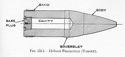
| 1328. Target projectiles.-Economy requires that target projectiles be made of the least expensive materials. They are therefore made of cast iron. A good grade of cast iron, and efficient methods of casting are necessary, however, to insure that the setback and centrifugal force do not cause fracture, either in the gun or in initial flight. They are so designed that they are similar to their prototypes in exterior shape, weight and balance. No economy can be secured in the rotating band, as it must function in the normal way. 1329. Proof shot, sometimes called “slugs,” are solid cast-iron shot with a square forward end. From the forward edge of the rotating band to the rear, they are identical in shape with the standard projectile of their caliber, but their only other similarity is their weight and bourrelet diameter. As a result of this design their behavior in the gun is similar to, while their flight is much shorter than, that of the standard projectile. They are used for proving-ground work and spotting practices. 1330. Line-carrying projectiles-These are simply loose-fitting slugs which carry a rod extending to the muzzle with an eye in the end, to which is attached a light cord. The projectile turns around immediately after clearing the muzzle and is held to its trajectory by the strain of the trailing cord. The cord is coiled down on deck and, after the projectile has passed over the target, a heavier line is bent to it and with succeeding heavier lines a hawser can finally be run. A range of about 350 yards can be secured in a 3-pounder saluting gun. |
 |