| GENE SLOVER'S US NAVY PAGES NAVAL ORDNANCE AND GUNNERY VOLUME 2, FIRE CONTROL CHAPTER 17 EXTERIOR BALLISTICS |
HOME INDEX
Chapter 17 Exterior ballistics
A. Forces Affecting Trajectories
B. Range Tables
C. Practical Application of Range Tables
D. Target-practice Post-firing Analysis
Chapter 17 Exterior ballistics
A. Forces Affecting Trajectories
B. Range Tables
C. Practical Application of Range Tables
D. Target-practice Post-firing Analysis
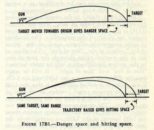
17B11. Danger space and hitting space
For a given target and trajectory, the danger space is the greatest
distance through which the target may be moved in the line of fire and
still be intersected at some point by that trajectory. Column 7 of the
range table is composed of values of the danger space for a target 20
feet high and of zero depth in the line of fire.
Referring to the 5”/38 range table, range 10,000 yards, it is seen that the
danger space is 18 yards. The value of the danger space at this range
for a target 30 feet high is 30/20 X 18 = 27 yards. Now if this 30-foot
target has a beam of 105 feet (35 yards) it is apparent that its danger
space is 27 + 35 = 62 yards.
Hitting space is defined as the variation in sight-bar range, at a fixed
target distance, between the trajectory which intersects a given target at
the waterline and the trajectory which intersects the top of the target.
Column 19 of the range table, headed “Change in height of impact for
variation of 100 yards in sight bar,” is the column used for determining
hitting space. (Sight-bar range is the range shown on the sight scale of
the gun at the instant of firing.)
To find the hitting space for a 20-foot target at range 10,000 yards, column 19 is entered, and the value obtained is 112 feet; i.e., a variation in
sight-bar range of 100 yards will move the point of impact 112 feet in the vertical plane of the target. To raise the point of impact 20 feet (to the top
of the target) the sight-bar range would have to be increased 20/112 X 100 = 18 yards.
This value for hitting space is the same as that earlier obtained for danger space. For most battle ranges, this relationship holds; for the shorter
ranges, however, there may be a considerable difference. For example with a 20-foot target at 3,500 yards the range table gives a danger space
(column 7) of 157 yards and a hitting space of 20/14 (column 19) X 100 = 143 yards.
B. Range Tables
17B1. Preparation of range tables
For service use, the Bureau of Ordnance publishes for each gun and for each projectile type fired by the gun a range table, which presents, in
convenient form for reference, the elements of the trajectories resulting from firing that specified projectile, at a specified initial velocity at various
angles of elevation under standard conditions (which will be described later). A range table tabulates, for each 100-yard increment of range, such
characteristics of the trajectory as angle of elevation, time of flight, angle of fall, and striking velocity.
It would obviously be impracticable to measure directly all the elements of the various trajectories, data for which appear in a range table. Neither
is there a single simple equation whose solution will give the characteristics of a trajectory at any point, principally because of complications
introduced by air resistance. The actual preparation of the range table involves experimental firings of a small number of the specified projectiles to
obtain data which are used in conjunction with a complex set of equations or formulas to solve the trajectory.
The equations require (in addition to values of initial velocity and angle of departure) a value known as the Ballistic Coefficient, C, for their
solution. This coefficient is a measure of comparison between the retardation of the specific projectile for which the range table is being prepared
and the retardation of a projectile of a specific standard form in air of an arbitrarily chosen standard density. The expression for C is:
C=w/id(squared)
where
w = weight of projectile in pounds.
d = diameter of the projectile in inches.
i = coefficient of form (the ratio of the retardation of the given projectile to that of a projectile of standard characteristics).
The retardation of the projectile of standard characteristics which is being used as a basis for comparison is available in either the form of a drag
coefficient or the form of a resistance curve. The data for such a drag coefficient or resistance curve are available from measurements obtained
by actual experimental firings of the standard projectile. It should be noted that i will include not only retardation relations based on form, but any
factors, other than weight and diameter, which affect retardation.
The value of the coefficient of form, i, is determined by experimental ranging at the Naval Proving Ground. A number of shots (from four to
seven) are fired at each angle of elevation in a series such as the following: 5°, 15°, 20°, 30°, 45°, and again at 15 degrees. The velocity is
measured at each angle. Throughout the firing, meteorological observations are made, at the surface and aloft, to determine wind, temperature,
and atmospheric density. On the basis of these observations computations are made for ballistic density and ballistic wind for the predicted height
of maximum ordinate. Since the projectile travels through various altitude zones, it is clear that values of wind, temperature, and density do not
remain the same throughout the trajectory. Therefore, fictitious values of wind and air density are computed which represent a constant value for
each over the entire trajectory. The fictitious values are called ballistic density, ballistic wind, and ballistic temperature; they are used for correcting
the trajectories derived from observed data to those which would exist in the arbitrarily defined standard atmosphere on which retardation of the
standard projectile is based.
Uncorrected observed ranges are recorded and averaged for each angle of elevation. These ranges are then corrected for errors due to: (1) the
height of the gun above tide level, (2) the curvature of the earth, (3) jump, and (4) rotation of the earth. These corrections are in addition to the
corrections for ballistic temperature, wind, and density mentioned above. The first two corrections mentioned in this paragraph permit the range
table to conform to the requirement that the point of fall be in the horizontal plane tangent to the earth at the gun.
The corrected observed values are used to obtain a final coefficient of form, 1, for each of the angles of elevation. From this the value of C for the
designed weight and diameter of the projectile can be computed.
The observed lateral deviation is corrected for the effect of the component of wind acting at right angles to the line of fire and for rotation of the
earth. The remaining deviation is the observed drift.
The formulas mentioned above can be used to solve for the elements at points on the trajectory, since the value of C is now available. Formerly,
these formulas were worked out and assembled in ballistic tables for a number of combinations of the variables involved. The entering arguments
of such a table are Eg, I. V. and C. From any combination of these three values it was possible to pick off the required values for the range table
such as Range, Time of Flight, Angle of Fall, Maximum Ordinate, etc. The ballistic table can thus be considered as a master range table. It should
be obvious that compilation of ballistic tables and construction of range tables from them entail much complicated and tedious work.
Current practice at the Naval Proving Ground is to compute all range table entries directly from the equations by means of large mechanical and
electronic computing machines. These machines are capable of handling a large number of complex solutions rapidly and accurately, thus
eliminating the need for ballistic tables. Obviously, in using computing machines in the preparation of range tables instead of using ballistic tables, a
different method of arriving at the desired value is used rather than a change in basic principle of solution of the trajectory.
The computation of drift for standard conditions is a separate calculation involving the use of the observed drift in a special formula.
17B2. Standard conditions for range tables
In the computations upon which range tables are based, certain arbitrary conditions are assumed. These arbitrary conditions are generally spoken
of as range-table standard conditions. In order to use the range table under conditions other than standard, it is necessary to provide in the range
table, corrections for variations from these conditions.
The standard conditions assumed for range-table values are that:
1. The projectile leaves the gun with the designed velocity.
2. The projectile is of the designed weight.
3. The atmosphere is of an arbitrarily chosen standard density.
4. There is no wind.
5. The gun is motionless.
6. The target is motionless.
7. The earth is motionless.
8. The gun and target are in the same horizontal plane, the plane tangent to the earth’s surface at the gun.
9. The gun is elevated in the vertical plane; that is, the axis of the gun trunnions is horizontal at the time of firing.
Since the range table is based upon these conditions, variations from any one of them may cause a significant error. In addition to the tabulation of
trajectories under standard conditions, the range table provides necessary corrections for variations from the first six of these standard conditions.
Corrections for variations from any of the last three require separate consideration or computation.
NOTE: Although motion of the target does not affect the trajectory itself, it enters into the problem of determining the trajectory that will reach the
target.
Correction for rotation of the earth can be computed from auxiliary tables published with range tables for major-caliber guns, or by fire control
instruments. The amount and direction of the error vary with the azimuth of the LOF, the latitude, and the range; but remain small in all cases. The
correction is disregarded for guns of 5-inch caliber or smaller. The effect of firing at a target not in the horizontal plane of fire was discussed in
article 17A6. The correction for tilt of the trunnion axis from the horizontal is practical only when using a mechanical solution and therefore is
considered in chapter 19. Use of the columns of the range table to account for nonstandard conditions will be taken up in the next section of this
chapter.
17B3. A typical range table
Appendix B contains extracts from the range table for the 8”/55 gun. The discussion which follows in this chapter, however, is based on the range
table for the 5”/38 gun, which appears in appendix C. The discussion in section C of this chapter, “Practical Application of Range Tables,” is also
based on the 5”/38 gun; and the tabular summaries of computations employ figures for the 5”/38 gun. A similar group of tabular summaries
employing figures for the 8”/55 gun appears as part 6 of appendix B. The student may refer to these summaries also during the following
discussion, since the computations are for the most part identical with those for the 5”/38 gun.
The range table shown in appendix C is for a 5”/38 caliber gun using a 55.18-pound AA common projectile. The table is based on an initial velocity
of 2,500 foot-seconds, which is the average velocity obtained throughout the service life of a gun, instead of the value of 2,600 foot-seconds,
which is the designed new-gun standard initial velocity. The use of such a base makes the required amount of correction from standard conditions
smaller, considering the life of the gun, and therefore promotes accuracy in the final results.
Columns 1 to 8, inclusive, of the range table give values of elements of the trajectory, under standard conditions, corresponding to a given range,
in increments of 100 yards. Columns 10 through 18 (there is no column 9) are needed because actual firing is seldom, if ever, conducted under
standard range-table conditions. To compute accurate values for Vs, (sight angle) and Ds (sight deflection) under actual firing conditions, it is
necessary to determine corrections to the trajectory for any variations from standard.
The errors tabulated in columns 10 through 18 of the range table are those caused by a variation of + 10 foot-seconds in initial velocity, -1 pound
of projectile weight, -10 percent atmospheric density, -10°F. in temperature, or 10-knot components of wind, target, or gun motion. The sign is
merely for convenience, so the tabulated values will usually be positive and not require a sign. Whether the correction is positive or negative will be
readily apparent under the particular set of conditions of the problem.
17B4. Column 10
Column 10 is headed “Change of range for variation of + 10 feet per second initial velocity.” The sole use of the plus sign in the heading is to
indicate the direction of the error in range resulting from a variation from standard initial velocity, an increase in initial velocity naturally causing an
increase in range.
The two elements which affect initial velocity are gun erosion and variation in powder temperature. Of these, erosion causes a loss in initial
velocity and a decrease in range. The Navy range tables are based on a standard powder temperature of 90° Fahrenheit. Since magazine ventilation
is regulated to ensure that the temperature in magazines hardly ever exceeds this figure, it is obvious that an increase in initial velocity due to
powder temperature seldom occurs. (It may occur if ammunition from ready lockers, located topside is used.) The variation in velocity due to
temperature variation of one degree from 90° F. is stated in certain range tables and other Bureau of Ordnance publications, a reduction in powder
temperature causing a loss in velocity. The loss of initial velocity per degree change of powder temperature will vary with the caliber and powder
index. However, 2.foot-seconds per degree F. change of powder temperature is about average, and will be used in this text for simplicity.
The loss of velocity caused by erosion is dependent upon the amount of bore enlargement, as was discussed in chapter 5 of this text. The range
table includes one graph which shows the amount of velocity loss for specified amounts of bore enlargement, which can be used following star
gaging, and a second graph showing bore enlargement versus equivalent service rounds fired, for use in periods between star gaging.
It must be noted that the loss of initial velocity for bore enlargement is, in the case of the 5”/38 caliber gun, a loss from new gun I.V. of 2600 foot-
seconds, 2500 foot-seconds being the average velocity during the life of the gun; therefore, in a relatively new gun, velocity change due to bore
enlargement may have to be computed, in relation to the range table, as a gain.
Having obtained the velocity loss from powder temperature and erosion data, as described above, one may determine the resulting range error
from column 10.
Example: Find the range error due to a loss of initial velocity of 126 foot-seconds from new-gun standard for the 5”/38 caliber gun, firing at a
range 10,000 yards.
Solution: From column 10, at range 10,000 yards, the error in range for a loss of velocity equal to 10 foot-seconds is -48 yards. A loss of 126
foot-seconds from 2,600 foot-seconds represents a loss of 26 foot-seconds from the range-table initial velocity. The error due to a loss of 26 foot-
seconds is 26/10 X (-) 48 = -125 yards, or 125 yards short.
Note: A shot falling short of the target is termed a short, while one falling beyond the target is an over. Shorts and overs are corrected by add and
drop spots, respectively.
17B5 Column 11
Column 11 is headed “Change of range for variation of -1 pound in weight of projectile.” This change of range is due to two causes which are
opposite in their effects. The first is the change in the initial velocity. A projectile heavier than standard will be expelled from the gun at lower than
designed muzzle velocity, causing a decrease in range. However, increase in weight will cause an increase in value of the ballistic coefficient and,
since retardation varies inversely as the value of the ballistic coefficient, this causes an increase in range.
Referring to the range table in appendix C, part 2, it is seen that at short ranges, the effect on initial velocity is the predominant factor, while at
long ranges, the effect on ballistic coefficient has the greater significance. At a range of 6,700 yards (in this table) the effects exactly cancel each
other and the net error is zero.
In practice column 11 is not normally used aboard ship. It would be used if projectiles of other than standard weight were to be fired. Projectiles
are required to be of designed weight within small tolerances, and the effects of these small variations are neglected, since it would obviously be
impracticable to weight each projectile or to make a correction for each gun before firing each salvo. It is apparent, however, that this variation in
projectile weight is one reason why all shots of a salvo, fired at the same time and under the same conditions, do not fall at the same point.
17B6. Column 12
Column 12 is headed “Change of range for variation in density of air of -10 percent.” For use under conditions where no aloft observations of air
density are possible, a table has been prepared based on the results of many past observations aloft. The entering arguments are the height of the
maximum ordinate in feet and the surface density; the result is the ballistic density. Standard surface density has been arbitrarily selected as the
density of the atmosphere which results from a temperature of 59° F., a barometric pressure of 29.53 inches of mercury, and a humidity of 78
percent saturation. This standard surface density is assigned a numerical value of 1.000. To determine the variation in the trajectory caused by
variation from standard surface density, the temperature and barometric pressure are measured at the surface and the resulting density is
expressed as a percentage of the standard. (Variations from standard percentage of saturation are neglected.) This percentage of standard density
at the surface is then used as an entering argument to the table of ballistic density (not shown in the appendix) and from it the ballistic density is
found.
The minus sign in the heading of column 12 indicates that a reduction in air density causes an increase in range, the plus sign in the column being
understood. Conversely, an increase in air density causes a decrease in range. In order to use the table for a given ballistic density, it is necessary
to compare the percentage variations from standard with the 10-percent variation from standard on which the column is based.
Example: Given ballistic density of 1.059, find from column 12 the range error resulting from the non-standard atmosphere, for the 5”/38 caliber,
2,500-foot-second gun, firing at a range of 10,000 yards.
Solution: The percentage variation from standard is l.059-1.000=(+) 0.059= (+) 5.9 percent. The value in column 12 is based on a (-) 10-per cent
variation from standard. The value taken from the column must, therefore, have a minus sign and the error is 5.9/10 X (-) 501 = -296 yards, or
296 yards short.
Note that the correction to compensate for this error in range is ADD 296 YARDS.
17B7. Use of the nomogram
An alternate means of determining the change of range for variation of air density is by nomogram. The nomogram provided with the 5”/38
caliber range table (appendix C, Part. 1) is an example of the type in use in the fleet today. When aloft aerological observations are not available, it
gives a rapid solution of the error in range due to variation in atmospheric density.
Instructions for its use are provided with the nomogram.
Example: Find the error in range for the 5”/38 caliber 2,500-foot-second gun, firing at range 10,000 yards, due to surface air temperature at 40
degrees F. and surface barometric pressure of 30.10 inches of mercury.
Solution: Alignment of 40° and 30.10” provides a point on the support line of the nomogram, which is the equivalent of determining the surface
density. Alignment of that point with 10,000 on scale R gives an error in range of -280 yards. The necessary correction is, therefore, ADD 280
YARDS.
The use of the nomogram is more accurate than results obtained from using column 12 with surface observations, as it takes into account the
ratio between mean measured and standard density for the actual maximum ordinate obtained.
NOTE: Some recent range tables, including the one reproduced in appendix C, have an additional column, 12a, which gives the change of range
for a variation of temperature of the air of -10° F. from the standard air temperature. The effect given in column 12a is that caused by change in
the elasticity of the air and is independent of and additional to the effect of any change in density. Column 12a is used with surface air
temperature; the standard being taken as 59 degrees F.
17B8. Columns 15 and 18
Column 15 is headed "Change of range for motion of target in plane of fire of 10 knots,’ and column 18 is headed “Deviation for lateral motion of
target perpendicular to line of fire, speed of 10 knots.” Actually, column 15 gives the distance that the target will move in the line of fire, if its
speed in the line of fire is 10 knots, during the time of flight of the projectile. Column 18 gives the same information for motion across the line of
fire. The values in the columns are derived by multiplying the speed of 10 knots, expressed as 16.89/3 yards per second, by the time of flight of
the projectile for the given range, as found in column 4 of the range table.
Example: Find the errors in range and deflection caused by motion of a target, the components of whose speed are 16 knots in the line of fire and
13 knots across the line of fire, the firing ship being on the starboard bow of the target, range 10,000 yards.
Solution: Since the values in both columns 15 and 18 are found by multiplying speed components of 10 knots by time of flight, these values are
identical, and are in this case 124 yards.
Then, in range, 16/10 X 124 = 198 yards that the target will move toward the firing ship during the time of flight. The correction to compensate
for this motion must be DROP 198 YARDS.
Across the line of fire the target will move 13/10 X 124 = 161 yards to the right, and the correction to compensate for this motion must be to the
right also.
It should be noted that target motion toward the firing ship will cause an error which is over in direction; also that target motion to the right will
cause the projectile to fall to the left of the target position at the end of the time of flight. The correction, in each case, is in the direction of motion
of the target.
17B9. Columns 13 and 16
Column 13 is headed “Change of range for wind component in plane of fire of 10 knots,” and column 16 is headed “Deviation for lateral wind
component of 10 knots.”
A wind, or wind component, in the plane of fire, or line of fire, is spoken of as a range wind. A lateral wind (wind, or wind component, blowing
across the line of fire) is spoken of as a cross wind.
The effect of a positive range wind (blowing in the direction in which the projectile is traveling) is to increase the range. The opposite is true for a
negative range wind. A cross wind will carry the projectile in the direction toward which the wind is blowing. The method of deriving the values
in these columns is quite involved, and will not be treated in this text.
The use of the columns is similar to that described in article 17B8, and will not be repeated. The direction of the errors having been found, care
must be taken to apply the corrections in the proper direction. The error is in the direction toward which the wind is blowing; hence the correction
must be in the opposite direction.
17B10. Columns 14 and 17
Column 14 is headed “change of range for motion of gun in plane of fire of 10 knots,” and column 17 is headed “Deviation for lateral motion of
gun perpendicular to line of fire, speed, 10 knots.” By “motion of gun” is meant the velocity imparted to the projectile due to motion of the firing
ship, aside from the velocity imparted by the powder charge.
This velocity may be positive or negative. Thus, a ship steaming at 10 knots and firing dead ahead imparts an added velocity of 16.89 foot-
seconds, in the horizontal plane. The same ship firing dead astern reduces the horizontal component of initial velocity by the same amount. Firing
on the beam causes a velocity component across the line of fire in the direction of motion of the ship.
If the gun were fired—and the projectile were to travel—in a vacuum, the range error could easily be determined. In the case of firing dead
ahead, the range would be increased by 16.89 X Tf/3 yards. But this is the value found in columns 15 and 18, since the target motion was
computed by using this very formula and with these same values.
However, the gun is not fired in a vacuum but in the resisting medium of the atmosphere. If no wind is blowing, a person standing on deck on a
moving vessel will feel an apparent wind, equal in force to the speed of the vessel. It may therefore be said that a projectile fired from a moving
vessel, in still air, is opposed by an apparent wind equal in force but opposite in direction to the motion of the vessel. The effect of such an
opposing wind may be found in column 13 for range wind and in column 16 for cross wind.
The above discussion leads to the statement that “the effect of a given component of gun motion is, numerically, the equivalent of the effect of an
equal component of target motion less the effect of an equal component of wind.” This does not mean that target motion, as such, enters into the
problem in any way. It does mean that the value of the change of range if the gun were fired in a vacuum, would be computed in the same manner
in which the effect of target motion is computed. This value is found in columns 15 and 18, which are tabulated as target motion. However, since
the gun is fired in air, this effect is opposed by a force which is the same as that of an equal component of wind blowing against the projectile.
This relation should be thoroughly understood, as it will be employed repeatedly in this text.
This statement may also be expressed as:
Column 14 = column 15 — column 13, and
Column 17 = column 18 — column 16.
Examination of any range table for any range shows that this relation is true. (The occasional difference of 2 or 3 yards is due to the fact that
columns 14 and 17 actually are computed from formulas, the results plotted, and the curves faired.)