| NAVAL ORDNANCE AND GUNNERY VOLUME 2, FIRE CONTROL CHAPTER 17 EXTERIOR BALLISTICS |
| HOME INDEX Chapter 17 Exterior ballistics A. Forces Affecting Trajectories B. Range Tables C. Practical Application of Range Tables D. Target-practice Post-firing Analysis |
| C. Practical Application of Range Tables 17C1. Definitions For shipboard firings, it is necessary to determine, or to estimate, the variations from range-table standard conditions as they exist at the time of firing, and to compute corrections for the errors caused by these variations. The individual corrections are summarized and the result is called a ballistic correction. Before this process can be described, it is necessary that the following terms be understood: Line of sight (LOS) is the straight line joining the sight and the point of aim. The line of fire (LOF) is the line joining the gun and the point of impact (or burst) of the projectile. The headings of some range-table columns speak of the “plane of fire,” others of the “line of fire.” The plane of fire is the vertical plane through the line of fire. In this section no distinction will be made between “line of fire” and “line of sight.” It will be noted that the difference between the LOF and the LOS, if the problem is solved correctly, is that the LOS is based on present target position at the time of firing, while the LOF is based on the predicted target position. The errors caused by constructing the angles for target, wind, and own-ship motion about the LOS instead of the LOF are negligible in the case of surface-target firing. Only in antiaircraft fire, where the target speed is very high and the sight deflection or lead angle may be very large is it necessary to differentiate between LOS and LOF. Relative target bearing (Br) is the direction of the target from the firing ship, relative to the bow of the firing ship. It is measured in a horizontal plane, clockwise from the bow of the firing ship to the line of sight, from zero to 360 degrees. True target bearing (B) is the direction of the target from the firing ship, relative to geographic north. It is measured clockwise in a horizontal plane from true north to the line of sight, from zero to 360 degrees. Target angle (A) is the relative bearing of the firing ship from the target. It is measured in a horizontal plane clockwise from the target’s bow to the firing ship, from zero to 360 degrees. (It must be understood that the line of sight, as defined above, is directional. To express the direction from target to firing ship, the expression “line of sight, reversed” is used. Thus, target angle is often defined as “the bearing of the firing ship from the target, measured from the target’s bow clockwise to the line of sight, reversed.”) True wind is the wind as it exists with respect to the earth and independent of any motion of the ship. Apparent wind is the wind which is apparent to an observing station which is itself in motion. It is the vectorial resultant of the motion of the true wind and the reversed motion of the observing station. Ballistic wind is a value of wind speed and direction which is considered to be the resultant of the effect of all the true winds acting upon the projectile in flight. Winds at various altitudes generally differ in force and direction from wind at the surface. Consequently, to calculate the effect of wind throughout the trajectory, it is necessary to measure, at regular increments of altitude, the actual force and direction of the wind, and to weigh the effect according to the length of time the projectile will travel through each stratum of wind. The resultant, computed as a vectorial sum, is used as though it were a uniform wind, constant throughout the trajectory. This method of determining ballistic wind is used at the Naval Proving Ground when ranging shots are being fired. Its use under service conditions is ordinarily impracticable except when an aerological unit is present, although an approximation may be obtained by following a balloon with an AA director. If no means is available for determining ballistic wind, corrections for wind are based on the existing surface wind. Wind direction is the direction from which the wind is blowing. The term is applied to either true or apparent wind. |
 |
| 17C2. The line-of-sight diagram In order to compute the errors caused by target motion, wind motion, and firing-ship (gun) motion, it is necessary to resolve these motions vectorially into components, in and across the line of sight. The diagram which is employed is called a vector diagram. A simple problem, with explanation of each step, will best illustrate how this solution is obtained. Given: 5”/38 caliber gun. Range, 10,000 yards. Relative target bearing, 300 degrees. Target angle, 80 degrees. Wind direction, true wind, 255° relative. Firing ship’s speed, 18 knots. Wind velocity, 10 knots. Target speed, 20 knots. Required: Draw the vector diagram for this situation; compute the components of gun, wind, and target motions in and across the line of sight. Determine whether the resulting errors will be over or short in range and right or left in deflection. Solution: a. Draw a vertical line representing the direction of the line of sight. This is always drawn as a vertical line with own ship (gun) at the bottom of the line. Mark the points, T, W, and G from which to draw vectors for target, wind, and gun motions, respectively. b. Since relative target bearing is 300°, the angle measured clockwise from firing ship’s bow to the LOS is 300 degrees. The gun-motion vector is drawn making this angle with the LOS. The acute angle between the gun’s vector and the LOS is seen to be 60 degrees. (The acute angle is used in the determination of the components.) By trigonometry, the component of gun motion in the LOS is 18 cos 60°, or 9.0 knots, and the component across the LOS is 18 sin 60°, or 15.6 knots, as shown in figure 17C1. The component in the LOS, in this case, results in imparting to the projectile an added velocity which causes increase in the range over that which would be attained were the firing ship stationary. Had the gun component in the LOS been in the opposite direction, or away from the target, the result would have been a decrease in the range. It must be stressed that motion of the firing ship after the projectile has left the gun can in no way affect the trajectory. What is of concern is the velocity (positive or negative) imparted to the projectile by the motion of the firing ship. In this case the range is increased, and the error is over. The vector should be so labeled. By the same reasoning, the gun motion component across the LOS imparts a lateral velocity and a deflection error in the direction of the component. In this case the error is right and the vector should be so labeled. c. From W lay off the true-wind vector for a wind direction relative to the bow of the firing ship equal to 255 degrees. (Since no compass courses or bearings were stated, the direction of the true wind could not be expressed as a true bearing.) The bearing of the LOS is 300° from the bow of the firing ship. Hence the direction from which the wind is blowing, with respect to the LOS, is 255° - 300° = (-) 45°. This angle is laid off at W, counterclockwise from the LOS. Since the wind is blowing from that direction through W, the wind vector is shown with its foot at W. Confusion in this vectorial representation very frequently arises because, by custom, we refer to the direction or bearing of the wind in the opposite sense to that indicated by the vector; i. e., the expressed direction is that from which the wind is blowing, while the vector indicates, as in all cases of motion, the direction toward which the movement is taking place. It is helpful to practice with examples in each of the quadrants and with different relative target bearings. Since the wind velocity is 10 knots, the component in the LOS is 10 cos 45° = 7.1 knots. The result of this wind component, acting on the projectile during the time of flight, is to cause a reduction in the range, or a short error. The component across the LOS, 10 sin 45° = 7.1 knots, blows the projectile to the right, causing a right error in deflection. The vector should be labeled short and right. d. From T lay off the target vector so that the target angle equals 80 degrees. The component in the LOS is 20 cos 80° = 3.5 knots, and across the LOS is 20 sin 80° = 19.7 knots. During the time of flight the target is decreasing the range at the rate of 3.5 knots, and a projectile fired with the given range setting will fall beyond the target’s position at the end of the time of flight. Hence the range error caused by this motion of the target is over. Also since the target moves to the right the projectile will fall to the left of the position of the target at the end of the time of flight, or the error in deflection will be left The vector is therefore labeled over and left. e. Having determined the direction of the errors, in range and in deflection, caused by gun, wind, and target motions, it is now necessary to determine, from columns 13-18, inclusive, the amounts of these errors in yards. It is convenient, however, to summarize these errors with the range errors caused by variations in initial velocity and atmospheric density, and with the deflection error caused by drift. 17C3. The gun ballistic correction In gunnery, a correction for an error in range or in deflection is known as a ballistic correction. The ballistic correction to compensate for the errors noted below is known as the gun ballistic correction. These elements are: In Range 1. Variation in powder temperature. 2. Velocity loss due to gun erosion. 3. Variation in air density. 4. Target motion in the LOS. 5. Wind motion in the LOS. 6. Guns velocity in the LOS. 7. Earth’s rotation (major caliber). In Deflection I. Drift. 2. Target motion across the LOS. S. Wind across the LOS. 4. Gun’s velocity across the LOS. 5. Earth’s rotation (major caliber) |
 |
 |
| The example given in article 17C2 will be continued to find the gun ballistic for that situation, with further variations due to powder temperature 80 degrees F., velocity loss due to erosion 18 foot-seconds (below 2,500 foot-seconds), and atmospheric density corresponding to surface air temperature 52° F. and barometer 30” .40. The multiplier for column 12 (variation in air density) is found by first obtaining from the aerological party a value of ballistic density factor, in this case 1.043. - 1.043 = -043 = (-) 4.3% Since column 12 is based on a 10 percent variation, the multiplier is (-)4.3/10, or (-) 0.43. The minus sign indicates that the range error will be short. The powder temperature is 10° less than standard, causing a velocity loss of 2X10=20 foot-seconds. The six range elements will be summarized: (See also appendix B, part 6.) Note the arrangement of column headings. Item 7 shows the sums of the over and short errors. Item 8 shows the algebraic sum of these errors (452-84=368), tabulated in the same column as the larger of the two. However, between items 7 and 8 the column headings are changed, so that the computed gun ballistic correction may be read as it will be used. Obviously a summation of range errors which is 368 yards short will require a correction of ADD 368 yards. The errors in deflection will now be summarized and the gun ballistic in deflection obtained. Note the change in column headings between lines 5 and 6. (See also appendix B, part 6.) The algebraic sum of the errors is 26 yards to the left. The shift in the column headings allows the computed gun ballistic correction to be read directly as right 26 yards. Caution must be exercised in reading the direction of the correction as shown directly above line 6, and not at the top of the column. As a last step, it is necessary to convert the ballistic correction in deflection from yards to mils. This is accomplished by dividing the correction in yards by the range in thousands of yards (26 divided by 10). Thus, in the example, the correction is right 0-3, which is the whole number of mils closest to 2.6. 17C4. Motion of own ship In the headings of range-table columns 13 and 16, neither true wind nor apparent wind is specified. If the gun were fired in a vacuum, the additional horizontal velocity imparted to the projectile by the motion of own ship would be equal in effect to equivalent target motion. However, the gun is fired in air, which for purposes of this discussion is assumed to be motionless. Now, the movement of own ship through this still air creates a wind apparent to a person on the ship. This apparent motion of the wind is equal in speed but opposite in direction to ship motion. Its effect is partially to nullify the extra velocity imparted by own ship, for it acts on the projectile just as though it were an actual wind. Thus, the effect of a component of own-ship motion (column 14 of range table) is numerically equivalent to the effect of an equal component of target motion (column 15 of range table) less the effect of an equal component of wind (column 13 of range table), as was pointed out in article 17B10. If true wind is used, gun motion, from columns 11 and 17, will include the effect of the wind set up by own-ship motion (column l4=column 15-col umn 13, and column l7=column 18-column 16). However, apparent wind, by definition, includes the effect of the wind set up by own ship’s motion. Therefore, if apparent wind is used, the use of columns 14 and 17 for gun motion would then result in correcting for this wind effect twice. Therefore, when apparent wind is used, gun motion is the numerical equivalent of target motion, since wind set up by own ship’s motion is incorporated in the apparent wind, and errors due to gun motion must be calculated using columns 15 for range and 18 for deflection. This is referred to as “treating gun motion as target motion.” (If a mechanical device is used for computing the effects of gun and target motion, the two motions are combined and treated as one, using correction based on columns 15 and 18. Wind corrections must then be based on apparent wind, using columns 13 and 16.) For an illustration assume that own ship and target are meeting head-on, each traveling at 10 knots, with no wind blowing (i. e., wind speed is zero), and range is 10,000 yards. The problem of range using true wind is solved as follows: (See also appendix B, part 6.) 17C5. Use of apparent wind Apparent wind is the vectorial resultant of the motion of the true wind and the reversed motion of the observing station (article 17C1). In the example given in article 17C2 (figure l7Cl), the relative target bearing was 300°, own ship’s speed 18 knots, and the true wind was from a direction of 255° relative, velocity 10 knots. The apparent wind is determined vectorially as illustrated in figure 17C2. |
 |
 |
 |
 |
 |
| The values of the components of this apparent wind are obtained by taking the algebraic sum of the true wind components, Xw and Yw, and the reversed own-ship components, of Xo and Yo. Figure 17C1 will now be revised to show apparent wind, the result appearing as figure 17C3. The combined components of gun and target motions in range are 9.0 + 3.5 = 12.5 knots, both components decreasing the range and causing an over error. In deflection the algebraic sum is 19.7 L - 15.6 R = 4.1 L. The net result is an error to the left. The gun ballistic correction can now be recomputed using apparent wind: (See also appendix B, part 6.) These results are practically identical with those obtained by the computation in article 17C3, indicating that the conclusions drawn in articles 17B8 and 17C4 are correct. The slight disparity between the results arises from the processes employed in the determination of values in the range table columns. The rule for use of columns can be restated as follows: True Wind Apparent Wind Target motion .. Col.15 and 18 Col.15 and 18 Wind ............. Col. 13 and 16 Col. 13 and 16 Gun motion .... Col. 14 and 17 Col.15 and 18 17C6. Use of true quantities In the conditions stated in the problem which was solved in articles 17C2 and l7C3, the firing ship’s course was not given, nor was it needed, since relative bearings of target and wind as well as target angle were employed, thus furnishing all data necessary for the construction of the vector diagram. In another type of problem a different statement of the conditions will be encountered. An example of this type will be solved as an illustration. Example: A ship, mounting 5”/38 caliber guns, steaming on course 225° (T) at speed 18 knots receives, during the night, information regarding the position of an enemy ship. The enemy is reported to be on course 265° (T), estimated speed 20 knots. It is predicted, by plotting, that at dawn the enemy will be in sight, at approximate range 10,000 yards, on bearing about 165° (T). Shortly before dawn the direction of the true wind is observed at 120° (T), velocity 10 knots. The average magazine temperature is 80° F., the velocity loss due to erosion from new-gun standard is 118 foot-seconds (or 18 f.s. from 2,500 f.s.) the surface air temperature is 52° F., and the barometer reading is 30”.40. Required: It is required to compute the gun ballistic for this situation, in order to open fire immediately if the enemy is sighted as predicted. Solution: In order to construct a vector diagram when true directions and courses are given, it is necessary to keep in mind that the LOS now has a true direction. This can best be done by putting an arrow on the LOS extended and labeling it with its true direction (in this case 165°) as shown in figure 17C4. Next lay off firing ship’s course 225° (T), from which it is seen that the acute angle between the LOS and gun’s vector is 60° (and that relative target bearing is 300°). Now lay off target course, 265° (T). It is evident that this course is 100° to the right of the LOS, and that the acute angle, and target angle, is 80 degrees. Finally the wind direction, 120°, is marked and the direction of the vector, as indicated, is thus 135°, to the right of the LOS, the acute angle being 45 degrees. Constructing the vector diagram, figure 17C4, from the data stated in the foregoing paragraph shows that it. is identical with figure l7Cl. The other conditions (powder temperature, erosion loss, air temperature, and barometer) are also as stated in articles 17C2 and 17C3. Therefore the result obtained in article 17C3, ADD 368 YARDS, RIGHT 26 YARDS, is the gun ballistic correction in this case as well. 17C7. Definitions of various ballistic corrections The discussion so far has been confined to the gun ballistic correction in range and deflection, for variations in the elements listed in article 17C3. These are the elements which will almost always be present in any practical case where the firing ship and target are moving, a wind is blowing, and corrections for the other variations from standard must be made. Ballistic corrections for elements not listed in article 17C3 may also be required. These ballistic corrections will be defined, with very brief explanations of their characteristics and of the necessity for their use. The control ballistic correction incorporates corrections which apply to the battery as a whole and which are caused by some artificiality in the method of control of the battery. In range and deflection the corrections that may be necessary are as follows: The sight-scale range-table correction. It may occur that a gun is fitted with an obsolete range scale, although an up-to-date range table is available. (A modification in projectile design might be the cause of this disparity.) The sight-scale range table correction will give the necessary correction to be applied to obtain a correct setting of the old sight scale at the given range. The correction is determined as follows: From the proper range table pick the angle of elevation, in minutes, corresponding to the desired range. Then enter the old range table, on which the sight scales are based, with this angle of elevation and note the corresponding range. The difference between this range and the desired range is the correction. If the range picked from the old range table is the greater, the correction is plus. The point-of aim correction usually arises in night firing or peculiar visibility conditions, when the point of aim must be one of the upper corners of the silhouetted target, while impact is desired at the center of the waterline. Another instance of this correction arises when a target is well beyond the horizon and the foretop (as an example) must be chosen as the point of aim, with impact desired at the center of the waterline. The method of determining this correction can readily be understood by reference to column 19 of the range table. The arbitrary ballistic correction, also called “arbitrary correction to hit (ACTH),” is designed to correct for errors not otherwise accounted for, which have consistently been noted in past gunnery practices, where accurate data as to ranges, target course and speed, and other elements were available for an exhaustive post-firing analysis. After all errors which can be accounted for (such as errors in rangefinder ranges and in estimates of target course and speed) have been eliminated, there will probably remain a certain error in the point of fall for which no cause can be definitely assigned. When enough data have been obtained and analyzed to provide an accurate estimate of this quantity, it is used as an arbitrary ballistic correction |
| The correction for first salvo only is necessitated by the fact that the initial round fired from a gun has a lower I. V., and therefore a shorter range, than succeeding rounds. This effect was at one time thought to be the result of the lower temperature of the bore; thus the correction has frequently and erroneously been known as “cold-gun correction.” It is now known that the loss of velocity is caused by oil in the bore; thus the correction is needed only if the bore has been cleaned and oiled since the last previous shot was fired. The amount of the correction is derived from experience, as is the ACTH, but it must be considered and treated separately, inasmuch as it is applied for the first salvo only and then removed. The total ballistic correction is the algebraic sum, in range and deflection, of the gun ballistic correction, the control ballistic correction (if any), and the arbitrary ballistic correction. The total ballistic correction for the first salvo is the algebraic sum of the total ballistic correction and the correction for first salvo only. The initial ballistic correction is a quantity applicable only when a gun (or battery of guns) is controlled by a fire control system that includes a computer or rangekeeper which computes some part of the ballistic corrections. Since almost all naval gunfire against targets is so controlled, this expression usually applies. It is defined as that part of the ballistic corrections not automatically compensated for by the fire control system. Modern computing instruments handle many of the ballistic corrections which make up the total ballistic correction. Those corrections which are not so handled must be computed by gunnery personnel, and applied by hand to the rangekeeper. If, as is the case in all present rangekeepers, the correction for gun and target motions is continuously computed mechanically, and the correction is introduced automatically into the value of the range and deflection scale settings before they are sent to the guns, it is apparent that the same corrections must not again be made. In the various types of rangekeepers to be studied in the fire control chapters, the elements of the gun ballistic for which correction is made by the rangekeeper mechanism will differ with the type of rangekeeper. The corrections which must be computed and separately applied as component parts of the total ballistic correction will therefore vary with the type of rangekeeper which is supplying the guns with range and deflection settings. In practice the computed corrections are incorporated into one correction called initial ballistic correction. Modern computing instruments handle many of the ballistic corrections which make up the total ballistic correction. Those corrections which are not so handled must be computed by gunnery personnel, and applied by hand to the rangekeeper. If, as is the case in all present rangekeepers, the correction for gun and target motions is continuously computed mechanically, and the correction is introduced automatically into the value of the range and deflection scale settings before they are sent to the guns, it is apparent that the same corrections must not again be made. In the various types of rangekeepers to be studied in the fire control chapters, the elements of the gun ballistic for which correction is made by the rangekeeper mechanism will differ with the type of rangekeeper. The corrections which must be computed and separately applied as component parts of the total ballistic correction will therefore vary with the type of rangekeeper which is supplying the guns with range and deflection settings. In practice the computed corrections are incorporated into one correction called initial ballistic correction. |
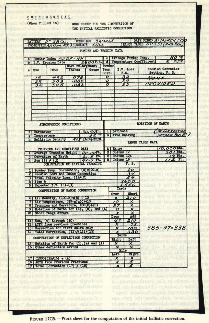
| 17C8. Computation of Initial ballistic correction Figure 17C5 is the work sheet for the computation of the initial ballistic correction filled in for a typical example. (See also figure B2 in appendix B, part 6.) Although the values are representative, they are not taken from an actual firing. The lines across the top of the sheet marked “Battery,” “Exercise,” etc., are for identification purposes, and the entries shown are self-explanatory. Powder and erosion data. As item a, “Powder Index,” enter on the sheet the powder index which appears on the powder card, thus identifying the powder used. Item b is "I. V. Erosion Data.” Enter the initial velocity which is used as the basis from which velocity loss is computed. Its value may be found from the erosion-data section of the applicable range table. (It should be noted that this entry may not be the same as the I. V. for which the range table was prepared. See art. l7B4.) Item c is “Average Powder Temperature.” Enter the average temperature of the magazine from which the powder is drawn. Item d, “Temperature Coefficient,” is the number of foot-seconds change of I. V. for each 1 degree F. change of powder temperature. It will be considered as 2 foot-seconds for the example given (see art. l7B4). If more accurate information on temperature coefficient is to be used, it will be found in OP 1004, which is carried in the gunnery department library of the ship. Space is provided in item e for entering erosion data for the individual guns to be fired. (In the example given, one gun of each twin mount in a destroyer main battery is considered.) Entries are made for the gun numbers, (guns in multiple mounts are usually numbered with the mount number plus the letters, L, R, or C to indicate the position of the guns) the “pseudo equivalent service round,” and bore enlargement or erosion-gage readings. note: The forms reproduced in figures 17C5 and 17D1, 2. and 3 are marked CONFIDENTIAL when filled in with data pertaining to an actual gunnery practice, and must be so treated. In this case, however, the data used are purely hypothetical. A review of chapter 5, section D, which discusses the manner of correcting I. V. loss due to erosion is required at this time, as is an understanding of the term “pseudo equivalent service round (PESR).” An equivalent service round has been previously defined as one which produces an amount of bore enlargement equal to that caused by a full-charge standard round. (Thus several reduced charges make up an equivalent service round) The PESR is the number of equivalent service rounds corresponding to the last accurate measurement of bore enlargement. When a gun is fired for the first time after star gaging, the PESR is not needed, since I. V. loss value may be obtained directly from the curve of I. V. loss against bore enlargement. Suppose, however, that several firings have taken place since bore gaging. In this event the number of equivalent service rounds which have been fired since the last bore gaging are determined. This number of equivalent service rounds is then added to the PESR. With this total of service rounds a corresponding bore enlargement is picked off the ESR-bore-enlargement curve, and from this value the total I. V. loss may be obtained as before from the bore-enlargement curve. If the temperatures of the various magazines from which the powder for individual guns is taken vary more than 2° F. from one another, entries should be made under the heading “Powder Temp. Corr.” and the I. V. loss due to this effect combined with the I. V. loss due to bore enlargement. If this is done, line 1 shown on the sheet must be left blank. In this example it is considered that the magazine temperature of all the magazines is 80°, and therefore the entry under “Powder Temp. Corr.,” item e, is zero, all loss of I. V. due to variation in powder temperature being accounted for under item 1 (i. e 20 f. s.). The important point to remember is that the effect of variation in I. V. due to change in powder temperature should not be corrected for twice. Since the entry under “Powder Temp. Corr.” in the example is zero, the entries under column marked “I. V. loss F. S.” will be the I. V. loss for each gun due only to bore enlargement, or 32, 34, and 35 foot-seconds respectively. In 5”/38 caliber guns, erosion connectors are not provided at the individual guns. This means that an average I. V. loss (34 f. s. in this instance) will be used in line 2, and the notation “None provided” will be made under the heading “Erosion Corrector Setting, F. S.” (If, however, as is the case in main-battery guns, individual erosion correctors are provided at the guns and compensation for gun erosion is made both at the guns and in the rangekeeper, the column marked “Erosion Corrector Setting, F. S.” would have the entry zero opposite the least eroded gun of the battery. Entries for the other guns would be the velocity loss in excess of that for the least eroded gun.) Atmospheric conditions. Item f is the barometer reading in inches, and item g is the temperature in degrees Fahrenheit. Both are surface readings taken from the ship’s instruments. Item h, “Ballistic Density,” is to be left blank unless it has been determined from actual measured data aloft or from an estimate made by an experienced aerologist. Trunnion and curvature data. It has been brought out that the angle of elevation to be set on a gun is normally applied from the LOS. When the target cannot be seen and no LOS is available (which often happens during shore bombardment), the angle of elevation is applied above the horizontal plane. This use of the horizontal plane gives rise to two additional errors at long ranges in surface fire, those caused by (1) the earth’s curvature and (2) trunnion height. Although the solution is correct for a target which lies in the horizontal plane tangent to the earth at own ship’s position, it will be in error if the earth’s curvature causes the target to drop below that horizontal plane, or if the fact that the guns are located high above the waterline causes the whole trajectory to be raised by the amount of such trunnion height above that horizontal plane. Therefore if the guns are laid with respect to a horizontal plane a correction is used, and it is necessary to fill in items i and j. Item i is the average height of the gun trunnions above the waterline. Its value can be obtained by reference to ship’s drawings. Data for item j can be obtained from an ordnance circular letter which gives curvature of the earth for various values of range. Item k is self-explanatory. Rotation of earth. This correction is omitted for guns of 5-inch and smaller caliber. When it is used, the value is to be found in a table which is entered with item 1, the latitude, to the nearest degree, item m, the true bearing of the target, and item A, the range. Range-table data. The best estimate of the present range to the target when the opening salvo is to be fired, is entered as item A. Using the value of range, item A, as an argument, items B, C, and D, columns 12, 12a and 19, respectively, are copied directly from the range table. Computation of initial velocity. Since, as stated above, the powder-magazine temperature for the three guns was the same, line 1 will be filled in this example. The algebraic sign from the formula as given is used. (i. e., the sign will be + in this instance, since item c (80 degrees) is less than 90). This is because, as will be noted in connection with line 3, velocity loss rather than correction for this loss is being computed. In line 2 is entered 34, the average foot-second loss of the three guns, determined from the column “I. V. Loss F. S.,” in item e. If compensation for erosion is made both in the computing instrument and at the guns, the value appearing in line 2 would still be “I. V. Loss F. S.” taken from item e, but would be the I. V. loss of the least eroded gun rather than an average value. The sign as given in this case, and almost always, is positive. In line 4 enter item b, 2,600 foot-seconds. The value which appears in line 5 is an algebraic sum. It is the’ expected initial velocity of the projectile and is set into the range-keeper or computer. Computation of range correction. The entry in line 6 has in this case been determined from the nomogram in part 1 of appendix B. (When the value of ballistic density as discussed in connection with item h has been entered as a percentage of standard density, which is considered as 100 percent, the formula in line 6 will give the proper value for entry in that line. If h is greater than 100, enter in the “short” column, if less than 100 enter in the “over” column.) Line 7 is the range correction for variation of air temperature from standard. If the algebraic sign from the formula is plus, entry is made in the “over” column; if minus, in the “short” column. The entry for line 8 (trunnion and curvature data), is always “over.” This correction is used only when the guns are being fired with respect to a horizontal plane (as in shore bombardment where the target cannot be seen), instead of with respect to a line of sight; in the example, the former is considered to be the case. Although no correction is made for rotation of the earth for 5-inch and smaller-caliber guns, a brief explanation is made here regarding the entry in line 9. Range tables for guns which require this entry have a table which, when entered with the arguments, latitude (item 1) and range (item A), and true bearing of target (item m), will give the value of correction to be entered in line 9. If the sign is plus, enter in the “over” column; if minus in the “short” column. Line 10, “other range errors,” is provided to account for certain range errors which are not normally encountered. A range error incident to the rangekeeper (computer) not being designed to compute data for the projectile which is to be fired, would properly be entered on this line. (Computations which involve the present range, expected I. V., and values taken from the range tables both (1) for the projectile being fired and (2) for the projectile on which the computer was designed, enter into determination of such an error and will not be detailed here.) Also, the automatic compensation in a rangekeeper (computer) made for certain elements is, under certain conditions, an approximation. Under such conditions, an appreciable error may result and should be accounted for in line 10. Applicable publications are available to enable evaluation of this error. In the given example the value of “other range errors” is considered to be zero. In line 12, ACTH (arbitrary correction to hit), is entered the correction in range which has been evaluated from previous firings, representing the value of consistently unaccountable errors. The entry for line 13 has been explained in section l7C7. Line 14 is self-explanatory. It is important to note that it is a correction rather than an error. It will be noted that this is taken care of by changing column headings to read “corrections” rather than “errors” after line 10. The correction thus derived represents that part of the initial ballistic correction in range which is not accounted for in the rangekeeper setting made in accordance with line 5. It will be noted that in the example the correction, as stated, can be used only for the first salvo. Succeeding salvos will take a correction of ADD 238 YARDS instead of 338 yards, as item 13 will no longer apply. This correction, in most fire control systems, is entered into the rangekeeper or computer as a range spot. Computation of deflection correction. Line 15, correction for “rotation of earth,” is zero in this example, since it is omitted for 5-inch and smaller-caliber guns. When used, the proper value is found in a table in the back of the range table similar to the one discussed in connection with range corrections. Line 16, “other deflection errors,” is governed by the same consideration as line 10. In general, if the rangekeeper (computer) is not designed for the projectile to be fired, the deflection difference will be so small that it can be neglected. However, an investigation should be made to verify this. In the example no other deflection errors are considered present, and the entry in line 16 is zero. The total correction in deflection, line 19, is the sum of line 17 which converts errors given on line 15 and 16 in yards to correction in mils, and line 18, which value is arrived at in the same manner as was described for line 12. The total correction in deflection constitutes the initial ballistic correction in deflection; it is entered into the computing instrument as a deflection spot. |
 |