Part C: Gun Directors
20C1. General
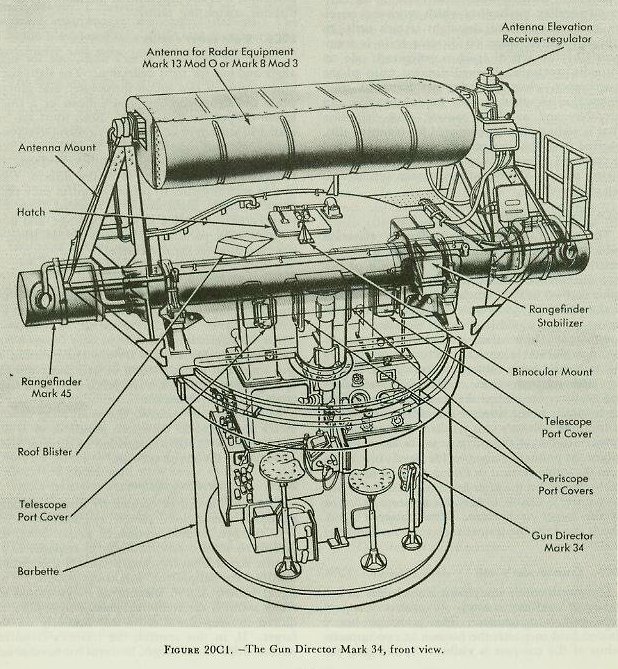
Each cruiser is equipped with two Gun Directors Mark 34-No. 1 forward and No. 2 aft, mounted near the main-battery fire control stations. The director is enclosed in a shield which supports the rangefinder and radar antenna as shown in figure 2OCl.
The directors may be used to measure the target coordinates (bearing, elevation, and range) in various manners, which must be defined.
Aiming is the process of establishing target position in bearing and elevation. Aim is classified as to type by the instrument employed: i. e., radar aim indicates the determination of bearing and elevation by radar; optical aim, by telescope. If, in association with determination of bearing by observation, elevation is determined by stabilizing instruments rather than by observation, the procedure is known as partial radar (or optical) aim. When neither bearing nor elevation is established by observation, but both by calculation of data otherwise introduced, the process is designated as generated aim.
Ranging is the process of establishing target distance from the firing ship. Like aiming, it is classified by means as radar ranging, optical (rangefinder) ranging, or generated ranging.
Both aiming and ranging may be either continuous or intermittent. Intermittent aim is directly associated with intermittent stabilization, and is therefore discussed in connection with the stable vertical in article 20E2. Intermittent ranging is employed when the means of ranging is by range-finder; it is rarely used with radar ranging.
Continuous aim and ranging may be classified as to method as automatic, aided, or manual. Manual aim and ranging signify the positioning of the instrument used by the operator by hand in accordance with his observations. Aided operation means the positioning of the instrument in accordance with signals received from the range-keeper, corrected as necessary by the operator as he observes the target (optically or by radar). Automatic ranging and aiming are not applicable to the system under discussion.
Each Gun Director Mark 34 is equipped to measure the three target coordinates, optically or with its associated radar equipment, and to transmit the values thereof (bearing and elevation after correction for parallax) to the rangekeeper. In addition, the director is equipped to take over some of the functions of the rangekeeper and stable vertical. It may be used to measure crosslevel optically. Under secondary fire control and auxiliary fire control procedures, and when supplied with sight angle and sight deflection from the auxiliary computer, the director can correct these quantities for trunnion tilt, combine them with level (director elevation) and director train respectively, and transmit the sums as gun elevation order and gun train order to the turrets via the main or auxiliary switchboards. In addition to these functions as instruments, the directors serve as lookout stations from which targets can be located and the fall of shot spotted.
20C2. Description
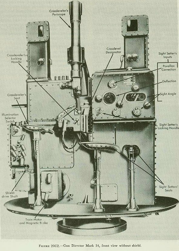
The director proper provides stations for a crew of eight men within the shield. At the rear of the director are stations for the trainer, pointer, spotter, and radioman. The rangereader’s seat is attached to the shield. At the front of the director (figure 20C2) are stations for the crossleveler and two sight setters. Each station provides a seat and the hand-wheels, switches, dials, optics, and other apparatus used by the operator. The spotter is provided with binoculars, which are mounted on the roof of the director shield.
The instruments and assemblies within the director include the following:
1. The trainer’s units.
2. The pointer’s units.
3. The crossleveler’s unit.
4. The sight setter’s unit.
5. The computing units.
6. The director drive system.
20C3. Trainer’s units
The trainer’s units are those which implement or facilitate tracking the target in bearing. They may transmit director train, train designation, and gun train order, and receive train designation and ownship course.
The trainer tracks a visible target by turning his handwheels to bisect the target image with his telescope vertical crossline, this training the director and determining director train. He may also use an auxiliary radar indicator for tracking the target in blind firing. As the director is trained, the radar antenna mounted on the shield turns with it. When the target echo on the radar scope is bisected by the center bearing line, the director is trained on the target, and the correct value of director train is determined. Director train is corrected by the horizontal parallax mechanism which receives a parallax range input from the sight setter’s unit. In primary control, corrected director train is transmitted by two sets of synchro generators; one set normally transmits observed director train to the rangekeeper, while the other set transmits train designation to other stations for information. In secondary and auxiliary control, deck deflection (that is, sight deflection corrected for trunnion tilt), received from the director computer unit, is added to corrected director train, and the result is transmitted by the observed-director-train synchros as gun train order.
20C4. Pointer’s units
The pointer’s units measure director elevation (which may be used as a substitute for level) corrected for vertical parallax. In one form of primary fire control, the director may substitute for the stable vertical in Plot, at which time the movement of the pointer’s handwheels operates synchro generators which transmit director elevation to the rangekeeper. In another, it transmits director elevation to the stable vertical in Plot for positioning the automatic firing contacts for automatic key firing, with selected values of level. In secondary and auxiliary fire control the pointer transmits level mechanically to the director computer units, which position the pointer’s unit synchros to transmit gun elevation order to the turrets via the switchboard. Follow-the-pointer dials provide level indication from the stable vertical in Plot or from an auxiliary stable element in the after fire control station, when the pointer is unable to keep his telescope crossline on the target or horizon. The pointer’s hand-wheels also keep the trainer’s telescope on the target in elevation.
20C5. Crossleveler’s unit
The crossleveler’s equipment is used only in secondary or auxiliary control. It consists of a periscope and a designator. The periscope has a divided field in which the horizon at two opposite points of the compass is visible. By bringing the images of the two parts of the horizon into line, the crosslevel is measured. The designator is a 36-speed follow-the-pointer dial which indicates crosslevel as received from the stable vertical, or the stable element in the after fire control station. When the pointers are matched, the crossleveler mechanically transmits this value of crosslevel to the computing units in the director, for the computation of trunnion-tilt correction in the formulation of gun orders. When crosslevel is measured by use of the periscope, it is also transmitted mechanically to the director computing units.
20C6. Sight setter’s units
here are two sight setter’s units, one for sight angle and one for sight deflection. The sight-angle unit consists of two follow-the-pointer dial groups, while the sight-deflection unit consists of a single follow-the-pointer dial group. Both units are operated in secondary and auxiliary control, receiving sight angle and sight deflection from the auxiliary computer in the fire control station, or from the rangekeeper, and relaying it to the director computing instruments. In primary control only sight angle is used. Sight angle is received from the rangekeeper, converted to parallax range, and used in computing parallax corrections for addition to observed director train and level.
20C7. Computing units
Mounted in the lower part of the director frame are two computing instruments, the trunnion-tilt corrector and the director-elevation corrector. These instruments are employed only in secondary and auxiliary fire control for the computation of gun train and gun elevation orders, using the following inputs: director train, level, crosslevel, sight angle, and sight deflection.
In primary fire control, the computing instruments are locked in their zero positions, so as not to interfere with the transmission of director train and level to the plotting room.
20C8. Director drive system
The director can be trained by three methods- automatic power, local power, and manual.
In the first method, automatic power drive, the director is trained automatically in response to an electric signal from the rangekeeper in Plot, which controls the amplidyne follow-up system.
This signal called
(delta (triangle) cB’r’, increments of generated director train. (I have written "triangle" as the website does not like the greek letter) is the computed change in bearing required to keep the director continuously on the target. If, in this control, the trainer’s crosslines tend to drift off the target, he turns his handwheels to bring the director back on target and signals Plot that a revision of estimated target quantities in the rangekeeper set-up is needed.
In local power drive the amplidyne follow-up system may be controlled by the trainer’s hand-wheels; or the trainer’s or spotter’s slewing controls may be operated to rotate the director rapidly through large angles of train.
In the two drive methods where power is employed, local and automatic, an amplidyne follow-up system is used.
In manual drive the trainer’s handwheels arc connected through a clutch to the training worm, and the director and shield are rotated solely by the power applied by the trainer to the trainer’s hand-wheels.
20C9. Shield
The director is enclosed and protected partly by the stationary barbette and partly by the rotating shield. The shield supports the rangefinder and the radar antenna, which turn with it.
20C10. Rangefinder and rangefinder equipment
The Rangefinder Mark 45 Mod 0 is a stereoscopic rangefinder with a base length of 18 feet. The range scale reads from 1,500 to 50,000 yards. Rangefinder range may be transmitted by means of the radar-range remote-control unit used in conjunction with the range indicator in this station. Two men operate the rangefinder-the spotter, who sights on the target and positions the wander marks, and the rangereader, who reads the range. The rangefinder is stabilized in level either manually, by means of a hand lever, or automatically. Automatic stabilization is accomplished by either of two devices: the rangefinder stabilizer or the rangefinder elevation receiver-regulator (whichever is installed). The rangefinder stabilizer is a self-contained device which includes a gyroscope and an electric-hydraulic follow-up system connected to the rangefinder through a linkage system. The elevation receiver-regulator follows a level signal received from the stable vertical in Plot (or from the auxiliary stable element), and thus stabilizes the rangefinder.
20C11. Radar equipment
Most of the radar equipment associated with the forward director is located in the plotting room; that for the after director is in the after fire control station. For either type of radar equipment an antenna mounted on top of the director shield is supported by the radar-antenna mount, which automatically stabilizes the antenna in level by means of a receiver-regulator. Level signals to this unit are relayed from the plotting-room stable vertical or the auxiliary stable element by the antenna-elevation corrector inside the shield. The operator turns a hand crank on the corrector to set the antenna at the desired elevation, after which it is held automatically in that position, regardless of roll or pitch. The radar antenna transmits a directed radar beam into space parallel with the director line of sight, and also receives target echoes. When the target echo is bisected by the center bearing line of the indicators, the director is on target. The antenna oscillates horizontally to scan an arc of 11.5°, ten times per second. The operator can substitute for the service antenna a dummy antenna and echo box, which are used for checking the performance of the radar.
20C12. Inputs and outputs
The inputs to the Gun Director Mark 34 in primary fire control are:
1. Increments of generated director train.
2. Generated director train.
3. Sight angle.
4. Own-ship course.
5. Level.
6. Train designation.
7. Observed range.
Outputs of the director in primary fire control are:
1. Corrected director train (corrected for horizontal parallax).
2. Director elevation (not always used).
3. Range.
4. Train designation.
The inputs to the director in secondary or auxiliary fire control are:
1. Sight angle.
2. Sight deflection.
3. Own-ship course.
4. Level (after director only).
5. Crosslevel (after director only).
6. Train designation.
Outputs of the director in secondary or auxiliary fire control are:
1. Gun train order.
2. Gun elevation order.
3. Corrected director train.
4. Range.
5. Train designation (secondary fire control only).
Back to top
