Part D: Fire Control Stations
20D1. General
There are two main-battery fire control stations- one located adjacent to the forward director and one near the after director.
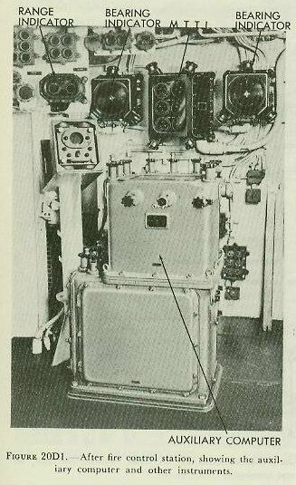
Figure 20D1 is a view of the after fire control station. Equipment in these stations supplies data to the directors when they are operated in secondary or auxiliary control, which makes them independent of the plotting-room equipment. Each station contains: an Auxiliary Computer Mark 3, which supplies sight angle and sight deflection to the directors; periscope mounts, used in locating targets; bearing indicators; multiple turret-train indicator, and various switches and signal lights. In addition, associated with the after fire control station is a Stable Element Mark 6, which supplies level and crosslevel to the after director for blind firing in secondary control or auxiliary control, and the radar control equipment associated with the after main-battery radar installation.
20D2. Computer Mark 3
One computer, such as that shown in
figure 20D1, is located in each fire control station. The computer is an auxiliary instrument for use in secondary or auxiliary control, or when the rangekeeper in the plotting room is inoperative. It is smaller and simpler than the Rangekeeper Mark 8. The predictions are less accurate than are those of the rangekeeper, and therefore more corrections may have to be introduced by hand. Unlike the range-keeper which produces gun orders, the auxiliary computer produces only sight angle and sight deflection.
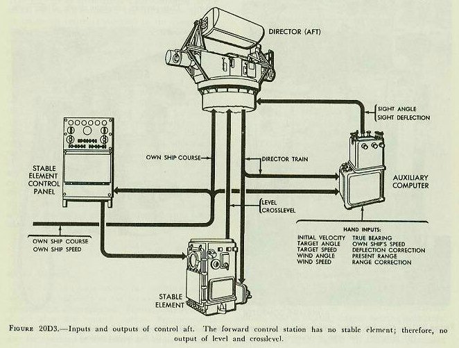
The auxiliary computer solves the fire control problem (for sight angle and sight deflection) for all movements of target and ship, and for wind across the line of sight. Director train is relayed to the computer by a target-bearing receiver.
Inputs and outputs of the auxiliary computer are shown in
figure 20D3.
In secondary control, sight angle and deflection are routed to the director through the main-battery switchboard, from which they are also transmitted to the turrets. In auxiliary control, the values are transmitted directly to the director, and must be telephoned to the turrets.
The computer in the after control station, by means of a range transmitter mounted on the computer, transmits generated change of range to the radar equipment in the same station. This quantity is used in the radar equipment in such a manner that aided range tracking is provided for the radar operator in both secondary and auxiliary control. This permits constant check of the computer solution with observed optical range and radar scope indications.
20D3. Periscope mount
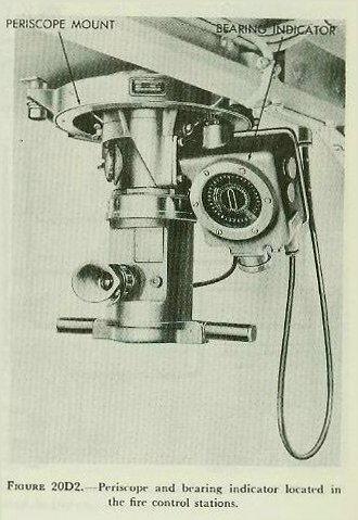
Each fire control station contains one or two periscope mounts. Each mount, as shown in
figure 20D2, supports a rotatable periscope, whose relative bearing angle is shown on an attached bearing indicator. The instrument is used for locating targets, and information thus obtained is telephoned to other stations.
20D4. Bearing indicator
The fire control stations each contain two bearing indicators, which are also shown in
figure 20D1. The bearing indicator indicates three quantities:
1. Relative target bearing, obtained by reading the fixed-dial graduations opposite the index on the ring dial.
2. True target bearing obtained by reading the inner dial graduations opposite the index on the ring dial.
3. Own-ship course, obtained by reading the inner dial against a fixed index.
Each bearing indicator receives director train from one of the aloft directors and own-ship course from the ship’s gyro compass.
20D5. Multiple turret train indicator
A multiple turret train indicator (MTTI) is shown in
figure 20D1 mounted on the forward bulkhead of the after fire control station. An identical instrument is provided in the forward fire control station. These instruments indicate modified turret train response for each of the three turrets on one set of dials, and show the difference between modified train response and gun train order on another set of dials. Modified train response is turret train corrected for horizontal parallax. Thus, the dials indicate whether or not the turrets are trained in accordance with gun train orders.
Back to top
