| NAVAL ORDNANCE AND GUNNERY, VOLUME 1 CHAPTER 6 GUN BARRELS AND INTERIOR BALLISTICS |
| HOME INDEX Chapter 6 Gun Barrels and Interior Ballistics A. Introduction B. Elements of gun design and maintenance C. Interior ballistics D. Erosion E. New developments in gun design |
| B. Elements of Gun Design and Maintenance 6B1. Modem requirements for gun power Present requirements for guns demand muzzle velocities of from 2,500 to 3,500 fps. Lower velocities give less striking energy. More important still, a projectile fired at low velocity would describe a curve so high in the air, for long ranges, that hits could not be made unless the range were known with great accuracy. Since the accurate determination of range is a critical problem in naval gunnery, the high-power gun is a necessity. High velocity of a projectile is produced, of course, by high pressure upon it while traveling through the bore. A gun may be considered as a tube designed to withstand a given pressure from within. In constructing such a tube, we must first consider what pressures it will have to withstand at the various points of its length, and then make it strong enough to insure perfect safety. The bore should also be of such material as to stand the wear and tear of firing a large number of rounds without being so damaged by expansion or abrasion as to interfere with the shooting. |
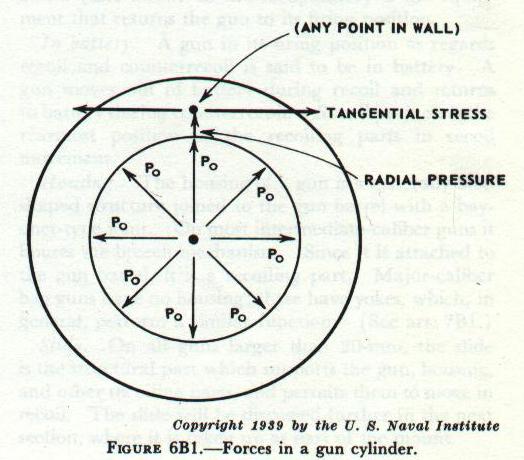 |
| 6B2. Stresses in a gun cylinder Considering a gun only as a cylinder, we find that the two principal stresses (fig. 6B1) to which such a cylinder is subjected upon the explosion of a charge are: 1. A circumferential or tangential stress or tension, coupled with a radial stress, tending to split the gun open longitudinally. 2. A longitudinal stress tending to pull the gun apart in the direction of its length. Experiments have shown that the greatest stress on the metal of the gun is the tensile stress set up in the direction of its circumference by powder gas pressure. In addition, the gun also experiences a longitudinal stress of relatively small value. If this longitudinal stress may be considered constant (and in guns it may be so considered without great error) we may lay down the first of “Lamé’s laws,” as follows: At any point whatever, in a cylinder under fluid pressure, the sum of the tangential tension and the radial pressure varies inversely as the square of the radius. This law says, in effect, that in a simple hollow cylinder under internal pressure, points in the metal close to the bore experience a large proportion of the stress, whereas those at a greater radius experience only a small proportion. This means that in a simple hollow cylinder composed throughout of metal of homogeneous physical properties, we soon reach a limit beyond which any thickness of wall aids but little in enabling the cylinder to withstand pressure. |
| Hence a modern gun would not be sufficiently strong to withstand the required pressure if made of a single simple hollow cylinder, however thick. But the gun must be built on a principle which will enable it to withstand more internal pressure than could be withstood by the simple cylinder type of construction. The problem is to make the outer layers take a proper proportion of the stress. In one modern solution to the problem, the gun is constructed of layers of metal. The layers nearer the bore are held under an initial compression by the tension of the outer layers. Thus, when the gun is fired, the inner layers must first be expanded sufficiently to remove the initial compression before they begin to experience a positive tension or stretch, while the expansion is continuously resisted by the tension of the outer layers. 6B3. Properties of gun steel Before considering the construction of a gun according to this principle, it will be necessary to examine some of the properties of gun steel which have not yet been considered. Gun steel is elastic within limits: thus, if a stress is applied so as to set up a strain (deformation or change in dimension) not exceeding the elastic limit of strain of the steel, then the steel will return to its original shape and dimensions when the stress is removed. It is then said to have been worked within its elastic range. However, when the elastic limit of strain has been reached, if the stress is increased the steel will yield rather suddenly and suffer a comparatively large strain without further increase in stress. Thereafter increase in stress will still further increase strain. The steel is now being worked in its semiplastic range. (If the stress is still further increased the strain will go beyond the semiplastic range and the steel will give rapidly and fracture, even with decrease of load.) The important point is that the steel has now received a permanent set or deformation. Nevertheless, it will attempt to return to its former dimensions when the stress is removed. In other words, it has suffered a deformation that is permanent but elastic. |
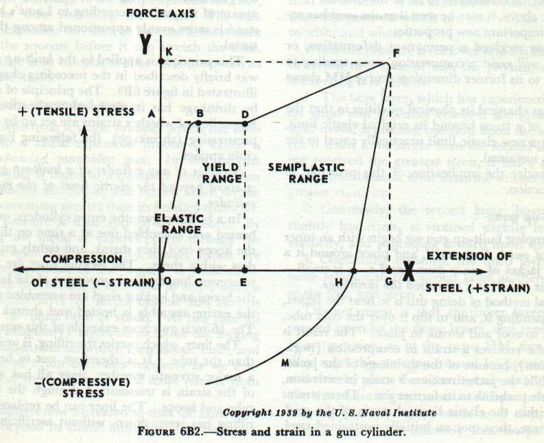 |
| These properties of gun steel are plotted in figure 6B2, in which the ordinates, measured along OY, represent the stresses applied to a test piece, and the abscissas, measured along OX, represent the corresponding strains set up. The curve is drawn only to show tension stresses causing extension strain in the steel, but it could be shown that the steel behaves similarly under compression stresses causing compressive strains. As the stress is raised from O to A, the steel is strained by the amount OC. If the load is increased slightly, the steel yields suddenly and suffers the additional strain CE at practically constant load. A further increase in the load to K causes an additional strain EG. The behavior of the steel thus far is represented by the curve OBDF. If the load is now removed, the curve is seen to return, not to the origin but to the point H, the line FH being about parallel to OB. The steel has taken the permanent deformation, or strain, OH but still has elastic properties, as is shown by the decrease in strain from G to H upon removal of the load. HG is somewhat larger than OC. If the same test piece is again stressed, a stress equal to OK will be required to strain it by the amount HG; for purposes of such a second stress, H may be considered to be at the origin. From the above, it may be seen that the steel has acquired two important new properties: (1) It has received a permanent deformation, or strain, and will resist a compression stress tending to compress it to its former dimension (curve HM shows this action). (2) It has changed its physical qualities in that the application of a stress beyond its original elastic limit, has given it a new elastic limit practically equal to the stress it has sustained. Now consider the application of this principle to gun construction. 6B4. Built-up guns In the simplest built-up gun we begin with an inner steel tube of outer diameter d, and place around it a cylindrical jacket of inner diameter d-s. s is small— on the order of 0.01 in.; s is called the shrinkage. The usual method of doing this is to heat the jacket, thereby expanding it, and to slip it over the cold tube, allowing it to cool and shrink in place. The result is that the tube receives a strain in compression (negative extension), because of the shrinkage of the jacket upon it, while the jacket receives a strain in extension, being unable to shrink to its former size. These strains are well within the elastic limit of strain of the steel. We have here, then, not an initially unstrained steel, but a compound cylinder of two members, the inner of which has an initial strain in compression (negative) and the outer an initial strain in extension (positive). When powder gas pressure (stress) is applied in the bore of such a compound cylinder, the pressure must first expand the tube enough to remove the initial strain of compression before it can continue the expansion toward the elastic limit of extension of the tube. Such expansion is continuously opposed by the jacket, which is pressing inward. This action may be stated in the following principle: If any pressure be applied to a compound cylinder, the strain at each point will be the algebraic sum of the strain at the point before the pressure was applied and the strain which the same pressure could cause at the corresponding point in a simple cylinder, of the same dimensions as the compound one. In a compound cylinder, according to this rule, the inner layer receives less strain in firing than would be received by the corresponding layer in a simple cylinder, for the original compression must first be overcome before any positive strain (extension) can be introduced. Correspondingly, the outer layer receives more strain than it would in a simple cylinder plus the original strain in extension that it receives in construction. The stress felt by the different layers of the gun is then no longer inversely proportional to the square of the radius according to Lamé’s law, but instead is more evenly apportioned among the layers of metal. |
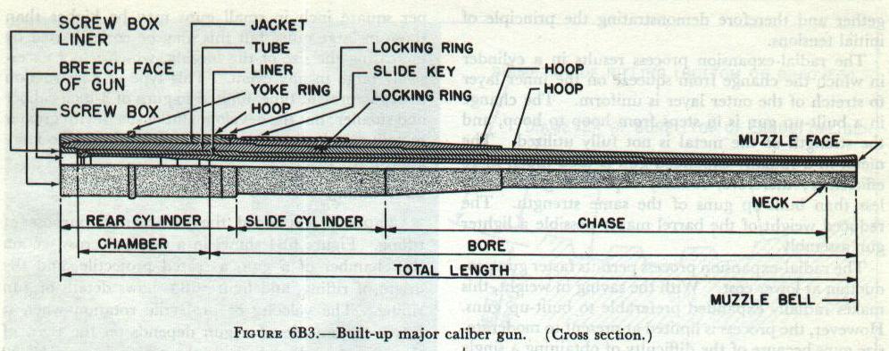 |
| This principle is applied in the built-up gun, which was briefly described in the preceding chapter, and is illustrated in figure 6B3. The principle of prestressing by shrinkage has its limits of application, however. Regardless of whether strains are set up by firing or by prestressing (shrinkage), the following limiting principle applies: No fiber of any cylinder of a built-up gun must be strained beyond the elastic limit of the metal of that cylinder. In a built-up gun, the outer cylinders, or hoops, are heated and assembled one at a time on the tube. As the hoops cool, they shrink, and tightly grip the cylinders within them. The locking rings are then added to prevent longitudinal movement of the hoops. After the hoops and locking rings are assembled on the tube, the entire assembly is heated and shrunk on a liner. The 16-inch gun is an example of this construction. The liner, which carries the rifling, is usually thinner than the tube. It is, therefore, not to be considered a major strength member, since all but a small part of the strain is transmitted through the liner to the tube and hoops. The liner can be replaced when the rifling has worn down, without sacrificing the other parts of the barrel which have a much longer service life. The assembled barrel forms a cylinder within which high pressure is developed as the charge explodes. The effect of the pressure is greatest on the inner cylinder, and diminishes rapidly as it proceeds outward. If the outer hoops were assembled over the tube without shrinkage, they would be subjected to less strain than the tube and the strength of gun would be little greater than the strength of the tube. However, the shrinkage of the hoops squeezes the tube, at the same time stretching the hoops. The safe pressure of explosion can then be increased, for it must overcome the squeeze before it can stretch the tube. The shrinkage is so calculated that each hoop carries a share of the strain. 6B5. Radially expanded guns A gun made from a single cylinder which has been subjected to a radial-expansion process is called a radially expanded monobloc gun. In this process the gun forging is bored to a diameter somewhat less than the finished dimension, and turned down on the outside to something greater than its finished diameter. Hydraulic pressure is then applied to the bore. By Lamé’s law the metal at various points through the wall of the gun will experience stresses which are inversely proportional to the square of their radii. The pressure in the bore is increased in steps, until a thin, indefinite layer of metal nearest the bore is brought to its elastic limit of strain. At this time all the other (imaginary) layers of metal in the forging are also strained, but all within their elastic limit, and the amount of strain decreases regularly as we consider layers of the metal more and more remote from the bore. The pressure is now increased so that the bore layer is strained, beyond its elastic limit, the layer next out-side the bore layer is brought just to its elastic limit, and the tension in all the other layers is increased. Still further increase of pressure increases the permanent strain in the bore layer (which is now being worked in the portion of the curve BDF, fig. 6B2), strains the second layer beyond its elastic limit, brings a third layer up to its elastic limit, and increases the tension in all the other layers. The increase in pressure is continued until the outside layer of metal just reaches its elastic limit of strain, and this pressure is held for a time. This pressure is considerably greater than the pressure which the gun will be called upon to withstand when fired. When the pressure h removed and the metal allowed to return to a state of rest, the physical condition of the forging is as follows: 1. The bore layer, which has experienced the greatest stress and therefore received the greatest permanent strain, is pressing outward upon the second layer, for it tends to be larger than the second layer. Having received the greatest stress, it has a greater permanent-and-elastic limit than the second layer, and a greater elasticity. 2. Conversely, the second layer, having received slightly less stress, is strained slightly less, has less elasticity, and is pressing inward upon the first layer. 3. Continuing outward, the third layer bears the same relation to the second layer as the second does to the first, and so on. The net result is that the ‘inner layers are being pressed upon by the outer layers, and receive a strain in compression, as in the curve HM, figure 6B2, but they resist this pressing inward by pressing outward, and thereby place the outer layer in a state of tension. We then have a gun constructed by a process of selfhooping (autofrettage), made as if composed of an infinite number of infinitely thin hoops shrunk together and therefore demonstrating the principle of initial tensions. The radial-expansion process results in a cylinder in which the change from squeeze on the inner layer to stretch of the outer layer is uniform. The change in a built-up gun is in steps from hoop to hoop, and the strength of the metal is not fully utilized. The metal in a radially expanded gun is used much more efficiently; therefore, radially expanded guns weigh less than built-up guns of the same strength. The reduced weight of the barrel makes possible a lighter gun assembly. The radial-expansion process permits faster gun production at lower cost. With the saving in weight, this makes radially expanded preferable to built-up guns. However, the process is limited at present to moderate-size guns because of the difficulty of obtaining a single forging large enough for those of major caliber. Typical monobloc barrels are found in the 5”/38 caliber guns and the 6”/47 caliber guns. 6B6. Combination guns The built-up and radially expanded methods may also be incorporated in a single gun. Thus the difficulty of obtaining a single forging big enough for the larger guns can be overcome. The 8”/55 caliber gun, for example, has a jacket shrunk on a radially expanded tube. 687. Simple one-piece guns Many small guns such as the 40- and 20-mm are made from a single steel forging which requires neither radial expansion nor hoops. The pressures developed per square inch in small guns may be higher than those in large guns, but this may be compensated by increasing the size of the forging, which is not excessively large in any event. This type of construction is, at the present time, limited to guns of 3-inch caliber and smaller; but the development of steels with greater metallurgical strength may make it applicable to large guns in the future. |
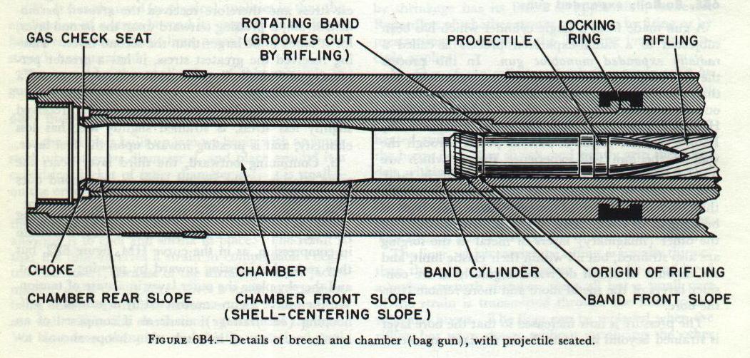 |
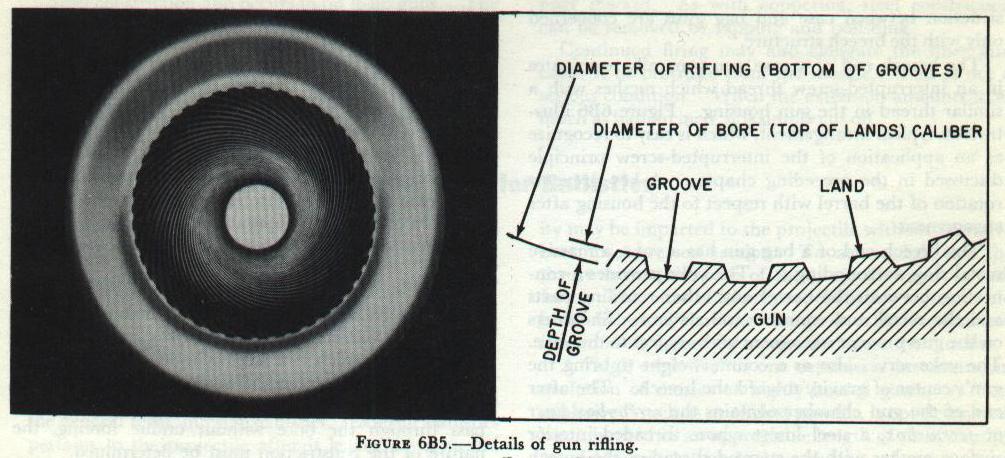
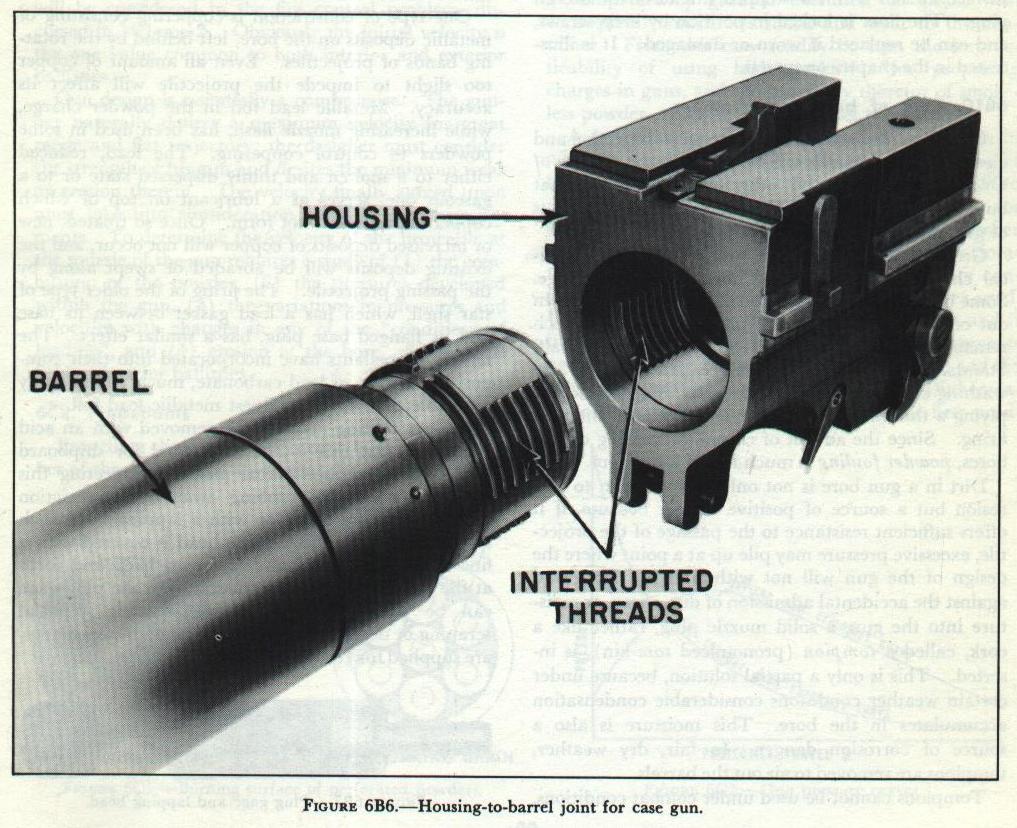
| 6B8. Rifling Chapter 5 explained the nature and purpose of rifling. Figure 6B4 shows in a detailed cross section the chamber of a gun, a seated projectile, and the origin of rifling, and figure 6B5 shows details of gun rifling. The velocity of projectile rotation when it leaves the muzzle of a gun depends on the twist of the rifling and the velocity of the projectile. A 16”/50 projectile turns at about 4,000 rpm when it leaves the muzzle, and a 40-mm projectile turns at about 40,000 rpm. In guns 5-inch and smaller, rifling is cut into the gun tube’s bore. Larger guns may be fitted with tubular loose liners, which can be replaced with relative ease when the rifling is worn out. The rate of rifling wear tends to increase with caliber. 6B9. Differences in construction between case and bag guns Nowadays only large guns (8-inch and up) use bag ammunition. Hence bag guns are generally of the built-up type, while a case gun may be monobloc or built-up, depending on size. Other differences in construction between case and bag guns are concerned only with the breech structure. The breech end of a case gun generally terminates in an interrupted-screw thread which meshes with a similar thread in the gun housing. Figure 6B6 illustrates a typical arrangement, which is easy to recognize as an application of the interrupted-screw principle discussed in the preceding chapter. A key prevents rotation of the barrel with respect to the housing after engagement. The breech end of a bag gun has a yoke, a massive metal ring, surrounding it. The yoke provides a connection between the barrel and other recoiling parts and the recoil and counterrecoil systems. Shoulders on the gun prevent movement with respect to the yoke. The yoke serves also as a counterweight to bring the gun’s center of gravity toward the breech. The after end of the gun chamber contains the screw-box liner or screw box, a steel insert whose threaded interior surface meshes with the stepped thread of the breech plug. The liner is locked in position by keep screws, and can be replaced if worn or damaged. It is illustrated in the chapter on turrets. |
 |
 |
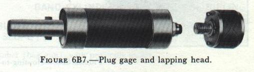
| 6B10. Care of bore and chamber Complete instructions for the regular inspection and cleaning of gun barrels will be found in the Bureau of Ordnance Manual and other publications of that bureau. Only a few of the more important aspects of gun maintenance will be discussed here. Great heat, great pressure, and complicated chemical changes accompany the burning of the charge. Some but not all of the residue of the burning is blown out of the muzzle after the projectile. That which remains in the gun is in the form of a corrosive salt. Standard procedure is to remove this “fouling” by washing out the bore with a hot soda solution and applying a thin film of oil before securing until the next firing. Since the advent of chromium plating of gun bores, powder fouling is much less of a problem. Dirt in a gun bore is not only an invitation to corrosion but a source of positive danger because, if it offers sufficient resistance to the passage of the projectile, excessive pressure may pile up at a point where the design of the gun will not withstand it. To guard against the accidental admission of dirt, spray, or moisture into the gun, a solid muzzle plug, rather like a cork, called a tompion (pronounced tom-kin), is inserted. This is only a partial solution, because under certain weather conditions considerable condensation accumulates in the bore. This moisture is also a source of corrosion danger. In fair, dry weather, tompions are removed to air out the barrels. Tompions cannot be used under combat conditions, because of the possibility of one inadvertently remaining in a gun when firing. However, dirt and water, especially salt water, must be kept out of the gun; so canvas, or in the case of small calibers, plastic, muzzle covers are used. In an emergency, the projectile can be forced through such covers without bursting the barrel. This procedure is, of course, subject to certain limitations. Projectiles with supersensitive nose fuzes cannot be fired through muzzle covers of any sort. In cold-weather operations, when canvas covers may become ice coated, they should be removed before firing. More immediately dangerous than corrosion or dirt is metallic constriction of the bore. Before and after each firing, barrels are tested for this condition with a plug gage, which is a steel cylinder accurately machined to slightly under the diameter of the bore. If at any time it is discovered that the plug gage will not pass through the bore without undue forcing, the nature of the constriction must be determined. One type of constriction is coppering consisting of metallic deposits on the bore, left behind by the rotating bands of projectiles. Even an amount of copper too slight to impede the projectile will affect its accuracy. Metallic lead foil in the powder charge, while increasing muzzle flash, has been used in some powders to control coppering. The lead, reduced either to a molten and thinly dispersed state or to a gaseous one, serves as a lubricant on top of which copper deposits will not form. Once so treated, new or increased deposits of copper will not occur, and the existing deposits will be abraded or swept along by the passing projectile. The firing of the older type of star shell, which has a lead gasket between its base and its flanged base plug, has a similar effect. The newest propellants have incorporated into their composition a trace of lead carbonate, much more readily reducible than even the finest metallic lead foil. Copper fouling may also be removed with an acid treatment, but this is not authorized for shipboard use. Approved mechanical means for meeting this condition consist of rubbing away the constriction with a wire bore brush or with a lapping head such as shown in figure 6B7. The head is covered with a fine abrasive material and is drawn back and forth at the location of the constriction until the plug gage can be passed through without forcing. Special scraping or decoppering heads, fitted with steel blades, are supplied for certain guns. |
 |
| Steel constriction also occurs in built-up guns. The friction of the projectile on the bore tends to drag the liner along with it, which tendency is resisted by the shoulders of the liner and the tube. With continued firing, the shoulders of the liner tend to override those of the tube, thereby forcing the walls of the liner inward. As with coppering, steel constriction can be removed by lapping and polishing. Continued firing may also elongate the liner and cause it to protrude from the muzzle. This is not a serious condition. When the extension amounts to as much as half an inch, it is simply cutoff. |