| NAVAL ORDNANCE AND GUNNERY VOLUME 2, FIRE CONTROL CHAPTER 16 RADAR AND OPTICS |
| E. Principles of Optics 16E1. Function of optical instruments The optical instruments used in naval fire control present a magnified image of the target to the observer’s eye. At the same time, the observer sees an image of a reticle, or reference mark, located inside the instrument itself. By accurately superimposing the reticle image on the target image, the observer can establish an accurate line of sight to the target. The rangefinder, by establishing two separate lines of sight, makes it possible to find the target range by triangulation. To form the reticle and target images, an optical instrument must control the path of the light that passes through it. It does so by the use of lenses, prisms, or mirrors, or some combination of these elements. This section briefly reviews the behavior of light as it passes through optical elements. Familiarity with these basic principles will make possible a general understanding of most optical instruments. 16E2. Nature of light Light is a form of energy. It travels from one point to another in the form of waves. Except for their wavelengths and frequency, light waves are identical with other types of electromagnetic radiation, such as radio waves and gamma rays. The wavelength of visible light ranges from approximately 0.35 micron to 0.70 micron. (A micron is one thousandth of a millimeter.) The color of light depends on its wavelength. In order of increasing wavelength, the colors are violet, indigo, blue, green, yellow, orange, and red. Radiation of longer wavelength than visible red is called infrared, or heat radiation. Beyond infrared are the radio waves. Radiations shorter than visible violet are, in the order of decreasing wavelength: ultraviolet, X rays, gamma rays, and cosmic rays. If a small object is dropped into water, a series of concentric circular waves will spread out from the point of impact. This provides a familiar analogy for the behavior of light waves. Waves in water, however, move on a two-dimensional surface; light waves move in three dimensions. The waves that move outward from a small source of light may be thought of as a series of concentric, rapidly expanding spheres. In the study of optical instruments it is convenient to trace the path of light rays, rather than waves. At any given point, a light ray is an imaginary line used to show the direction in which the light wave is moving. Since the wave is an expanding sphere, its direction of movement at any point is along a radius of that sphere. A ray, then, is a radius of the sphere formed by the wave front, and is at right angles to the wave front. |
| INDEXCHAPTER 16 RADAR AND OPTICS A. Introduction B. Principles of radar C. Types of radar equipment D. Special purpose equipments E. Principles of optics F. Types of optical equipment G. Combat information center (CIC) |
 |
 |
 |
 |
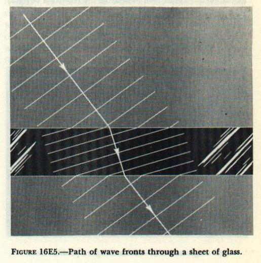 |
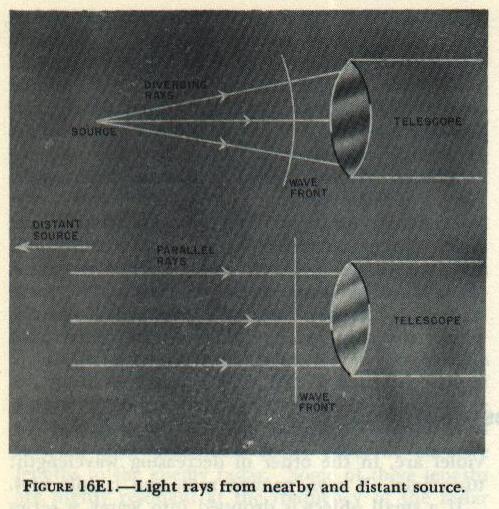
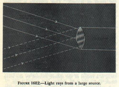
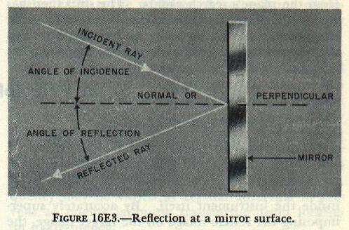
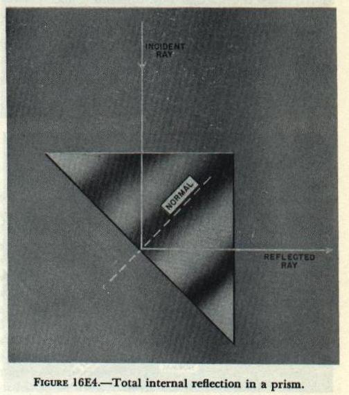
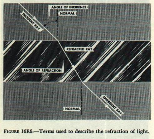
| A telescope or similar instrument will receive only a small part of the light emitted by the source. Each wave that enters the instrument, therefore, is only a small part of a sphere. If a wave comes from a nearby source, the part of it that enters the instrument will be strongly curved. And the rays (radii of the spherical wave) that enter the instrument will be diverging. But if the source is at a great distance, the part of the wave that enters the instrument will be nearly flat; for all practical purposes it can be considered a plane. Since the rays are perpendicular to the wave front, the rays that enter an optical instrument from a distant point can be considered parallel. Figure 16E1 should make this clear. In figure 16E1, the source of light is a single point. But a telescope is most often used to observe fairly large objects, such as enemy ships. In this case, of course, not all the rays that enter the telescope will be parallel. But all the rays that enter the instrument from any one point on the object will be parallel, as shown in figure 16E2. In this figure, the solid lines represent rays from the top of the object; the broken lines represent rays from the bottom of the object. Note that in all three drawings only a few rays are used to represent the light that enters the instrument. It should be remembered, however, that light enters an optical instrument at every point on its first lens. Since the spherical wave has an infinite number of radii, an infinite number of rays are striking the lens. In diagrams of optical instruments, only a few of these rays will be shown. Three rays are usually enough to show the path of light, and the formation of images, within the instrument. Light travels at tremendous speed: approximately 186,000 miles per second in air. In a vacuum, its velocity is slightly higher. In a denser medium, it moves more slowly. For example, the velocity of light in water is about 140,000 miles per second; in glass it ranges from 95,000 to 127,000 miles per second, depending on the optical density of the glass. When light passes from one medium into another of different density, its velocity changes. This change in velocity makes its possible for an optical instrument to control the path of light, to form images, and to magnify them. 16E3. Reflection When light, traveling in air, strikes the surface of a mirror, most of it is reflected back into the air. Figure 16E3 shows the path of a ray of light reflected by a mirror. This figure illustrates several of the terms used to describe the reflection of light. The incoming ray is the incident ray. The normal is an imaginary straight line, at right angles to the mirror surface, passing through the point of incidence. The angle of incidence is the angle between the incident ray and the normal, and the angle of reflection is the angle between the normal and the reflected ray. The law of reflection states, first, that the angle of incidence is equal to the angle of reflection; and, second that the incident ray, the reflected ray, and the normal all lie in the same plane. When light, traveling in air, strikes the surface of clear glass, a part of the light will be reflected back into the air; the rest will enter the glass. If the incident ray lies on the normal (zero angle of incidence), about 5% of the light will be reflected. As the angle of incidence is increased, the amount of reflection increases. As the angle of incidence e approaches 90°, the reflection approaches 100%. When light, traveling in glass, strikes an air surface, a part of the light will be reflected back into the glass; the rest will enter the air. At zero angle of incidence, about 5% of the light will be reflected back into the glass. As the angle of incidence is increased, the amount of reflection increases rapidly. When the angle of incidence becomes greater than the critical angle, all of the light will be reflected back into the glass; none of it will enter the air. (The. critical angle for various types of glass, at an air surface, varies from 37° to 43°.) For angles of incidence greater than the critical angle, the inner surface of the glass acts like the mirror in figure 16E3, and the reflection from this surface follows the same laws. This property of a glass-air surface, called total internal reflection, is used in many optical instruments. Mirrors are occasionally used in optical instruments to deviate the line of sight. But, if the angle of incidents is greater than the critical angle, internal reflection at a glass-air surface is usually used for this purpose. Figure 16E4, for example, shows how the line of sight may be deviated through an angle of 90° by internal reflection at the diagonal face of a right-angle prism. For this purpose, a prism has two important advantages over a mirror. First, a prism may be more rigidly mounted than a mirror, and is thus less subject to misalignment or breakage. Second, the reflecting surface of a prism will reflect all the incident light, whereas a mirror will reflect only about 90%. An inspection of figure 16E4 will show that if the prism is rotated (in the plane of the page) through any angle, the angle of incidence will be changed by the same angle. The angle between the incident ray and the reflected ray will therefore be changed by twice that amount. If a pointer is attached to the prism, it can be made to indicate, on a suitable calibrated scale, the angle through which the line of sight has been deflected. 16E4. Refraction of light When light passes from air into glass, its will decrease. It will resume its original when it leaves the glass and enters the air. If a ray of light strikes an air-glass or a glass-air surface at an oblique angle, its change of speed will result in a change of direction. Figure 16E5 shows why this is so. The diagonal lines in the figure represent the approaching light waves. Since they are coming from a distant source, they are parallel. As each wave enters the glass, various points along the wave front will slow up successively, and as a result the entire wave front will change its angle. Since the direction of movement, shown by the ray, is at right angles to the wave fronts, the light bends as it enters the glass. The opposite effect occurs when the waves leave the glass. Now the various points along the wave successively increase their speed. As a result, the emergent waves are parallel to those that entered the glass. And the emergent ray is parallel to the incident ray, although it has been displaced to one side. Figure 16E6 illustrates some of the terms used to describe the refraction, or bending, of light. The law of refraction states that light bends toward the normal when it passes into a denser medium; it bends away from the normal when it passes into a less dense medium. The exact angle of bending may be easily calculated. It depends on the angle of incidence, and on the optical density of the two media. Optical density is expressed as index of refraction. (The index of refraction of a vacuum is one; the index of refraction of air is approximately one. The various types of optical glass range from approximately 1.5 to 1.96.) |
 |
 |
 |
 |
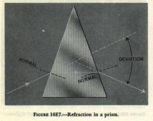
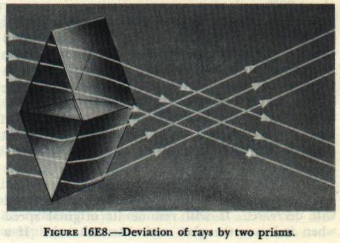
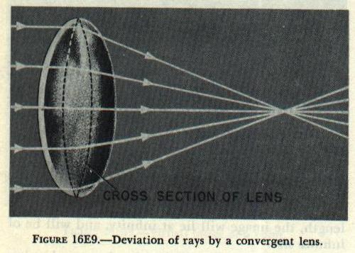
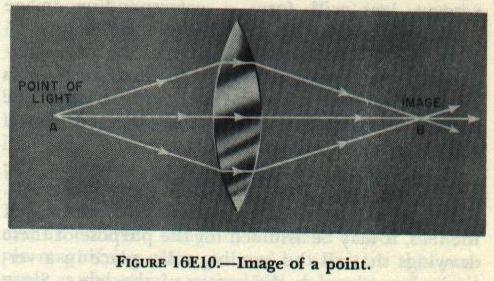
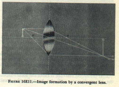
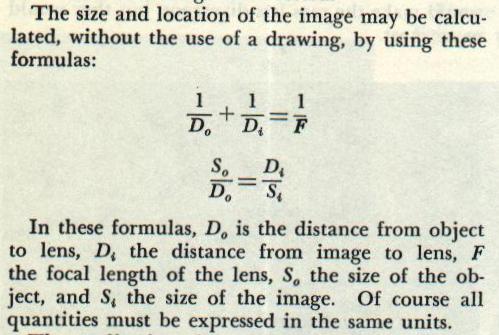
| When the two glass surfaces are parallel, as in figure 16E6, the emergent ray is parallel to the incident ray. When such elements occur in optical instruments (as, for example, in the end windows of rangefinders), they do not deviate the line of sight. However, if the two glass surfaces are not parallel, the line of sight will be deviated, as in figure 16E7. When the ray enters the glass at the first surface, it bends toward the normal. As it leaves the glass, at the second surface, it bends away from the normal. The net result is a deviation of the ray toward the base of the prism. Thin prisms are used in rangefinders to deviate the line of sight through a small angle. 16E5. Image formation Figure 16E8 shows the path of parallel rays of light on passing through two prisms mounted base to base. Each ray will be deviated toward the base of the prism it passes through. As a result, the upper rays are deviated downward, and the lower rays are deviated upward. All the rays emerging from the upper prism are parallel, and all the rays emerging from the lower prism are parallel. If the surfaces of the two prisms in figure 16E8 are rounded off to form a convergent lens, as in figure 16E9, each ray will have a different angle of incidence, and will therefore bend to a different degree. The ray that passes through the center of the lens is normal to both surfaces, and therefore does not bend. Such a ray is said to lie on the optical axis of the lens. Rays near the axis will strike each surface at a small angle of incidence, and will be slightly deviated toward the axis. The greater the distance from the axis, the greater the angle of incidence at each surface, and the greater the deviation toward the axis. If the lens is perfect, all rays parallel to the axis will meet at a single point, called the focal point of the lens. Every lens has two focal points, one on each side. (If the rays in figure 16E9 were coming from the right, they would meet at a point on the left side of the lens.) The two focal points are equally distant from the lens. The distance from either focal point to the center of the lens is the focal distance, or focal length of the lens. By applying the law of refraction at each surface of the lens in figure l6E9, it can be seen that, if a source of light is placed at the focal point, the diverging rays that strike the lens will be deviated toward the axis, and will be parallel when they emerge from the lens. The behavior of light on passing through a convergent lens can be summarized by these statements: parallel rays will be converged to the focal point, where they will cross; convergent rays will be more strongly convergent after passing through the lens; divergent rays will be less divergent after passing through the lens. Figure l6ElO shows three rays of light diverging from a point source, and passing through a convergent lens. It should be remembered that an infinite number of rays are striking the lens, but as usual three are enough to show what happens. All the rays from A that pass through the lens converge and meet at point B. Point B is therefore the image of A. Note that B is itself a source of light, since rays diverge from it just as they do from A. If a sheet of paper is held at B, the image may be seen as a bright point on the paper. If B lies between the lens and the observer’s eye, the image may be inspected directly. In figure l6ElO it is obvious that the distance from point A to the lens is greater than the focal length. If the source were at the focal point, the rays emerging from the lens would be parallel, and would meet only at infinity. If the source were closer to the lens than the focal point, the lens would make the rays less divergent, but they would never meet. A target or other object is visible when it reflects light toward the observer. Each point on the target, unless it’s black, may be considered a point source of light. For each of these points, a convergent lens will form a corresponding image point, behind the lens. These image points together form a recognizable image of the whole target. In the study of any optical instrument, it is often desirable to know the size and location of the image. This information may be obtained from a scale drawing, as in figure 16E11. In this figure, the target is an arrow lying to the left of the lens, with its tail on the optical axis. Although refraction takes place at both surfaces of the lens, it may be assumed for the purpose of these drawings that all the bending takes place in a vertical plane through the center of the lens. Since the tail of the arrow lies on the optical axis, the tail of the image will also lie on the axis. It is therefore possible to determine the size and location of the whole image by locating the image of the arrow head. Although an infinite number of rays from the arrow head are striking the lens, it is possible to plot the exact path of three of these rays by using these rules: 1. Any ray that passes through the center of the lens will not be deviated. 2. Any ray that passes through the first focal point will emerge parallel to the axis. 3. Any ray that strikes the lens parallel to the axis will pass through the second focal point. Obviously, the image of a single point may be located by using any two of these three rays. In figure 16E12, the size and location of the image is determined by plotting the path of two rays from the top of the target, and two rays from the bottom. Note that the image is inverted. |
 |
 |
 |
 |
 |
 |
 |
 |
 |
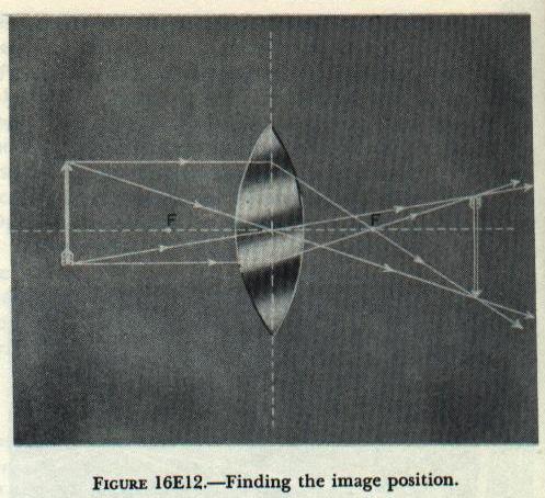
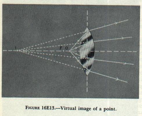
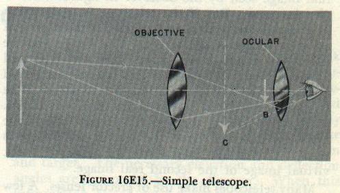
| In these formulas, Do is the distance from object to lens, D4 the distance from image to lens, F the focal length of the lens, So the size of the object, and S4 the size of the image. Of course all quantities must be expressed in the same units. The application of these formulas will reveal several things: 1. If the object distance is twice the focal length, the image distance will also be twice the focal length, and the image will be the same size as the object. 2. If the object distance is equal to the focal length, the image will lie at infinity, and will be of infinite size. 3. If the object distance is more than one but less than two focal lengths, the image distance will be greater than two focal lengths, and the image will be larger than the object. 4. If the object distance is greater than twice the focal length, the image distance will be more than one but less than two focal lengths, and the image will be smaller than the object. 5. If the object distance is less than the focal length, the image distance will be negative, indicating that no real image is formed. 16E6. Virtual images Figure 16E13 shows the path of several rays diverging from a point source of light, O, when the source lies between the lens and its first focal point. These rays are highly divergent. The lens makes them less divergent, but it does not have the power to bring them to a focus. However, an observer on the right side of the lens may see the point O by looking through the lens. Since the observer is accustomed to assuming that light travels in straight lines, it will appear to him that the rays from source O are actually coming from point I. Point I is therefore an image of O. However, if a sheet of paper is held at I, no image will be formed on the paper. Point I is therefore not a real image. No rays actually diverge from I, as they do from a real image; they merely appear to diverge from I. Point I is said to be a virtual image of point O. Note that the virtual image is farther from the lens than the object itself. Figure 16E14 shows how a scale drawing may be used to determine the size and location of a virtual image. The object is the small arrow between the first focal point and the lens, with its tail on the axis. The drawing plots the actual path of two rays from the arrow head. If the two emergent rays are continued backward to the left of the lens, they will intersect at the image of the arrowhead. Note that, whereas the real image formed by a convergent lens is inverted, the virtual image is erect. The two formulas given in article 16E5 may be used to calculate the size and location of the virtual image. The calculated image distance will be negative, indicating that it lies to the left of the lens. The drawing and the formulas both reveal that the image is larger than the object. A single convergent lens may be used, therefore, as a simple magnifying glass. A magnifying glass is most effectively used by holding it close to the eye. The object distance is adjusted until the image appears in sharp focus when the muscles of the eye are completely relaxed. The object distance will then be equal to the focal length of the lens, and the virtual image will lie at infinity. 16E7. Simple telescope A telescope is used to provide, to an observer’s eye, an enlarged image of a distant object. A simple magnifying glass can not be used for this purpose; as shown in article l6E6, a lens may be used as a magnifying glass only when the object under the observation is at or closer than the focal point. As previously stated, a convergent lens may be used to form a real image, which may be examined by the observer. But this real image would appear to the observer as no longer than the object itself. Obviously, then, a single lens cannot be used to provide an enlarged image of a distant object. However, a telescope can be made by using a combination of two or more lenses. The first lens, called the objective, forms a real image of the distant object. Since rays diverge from this real image just as they do from the object itself, the observer may examine the real image through a second lens, called the ocular. The ocular serves as a simple magnifying glass. It forms an enlarged virtual image of the real image formed. by the objective. Figure 16E15 shows the path of rays through a simple telescope. The arrow at the left of the drawing is the target. Actually, it is at a considerable distance from the telescope: it is shown as a nearby object so that the rays diverging from it may be traced through the telescope. The drawing shows two rays from the head of the arrow. These rays are converged by the objective to meet at point B. A real, inverted image of the target therefore lies in a vertical plane through B. After crossing at point B, the two rays diverge and strike the ocular lens. Because this lens is close to B, it cannot converge the rays to a point again. However, it does make these rays less divergent. To the observer’s eye, these two rays appear to diverge from point C. The virtual image seen by the target therefore lies in a vertical plane through C. The ocular is usually adjusted so that this image is at infinity; the drawing shows the image at C only for convenience. To the observer, the virtual image appears to be considerably larger than the object itself. The telescope therefore forms an enlarged image of the distant object. The two lenses are, of course, suitably mounted in a metal tube. In some instruments, the ocular is so mounted that the observer may adjust its distance from the objective. This is sometimes necessary, because the position of the real image depends on target distance. The closer the target is to the telescope, the farther the real image will be from the objective. The observer must adjust the position of the ocular until its focal point lies in the plane of the real image. The virtual image will then appear in sharp focus when the observer’s eye is relaxed. In other instruments, for example the gun. sight telescope, this focusing adjustment is unnecessary. Since the target is always at a considerable distance, the distance between the objective lens and the image it forms is practically constant. |
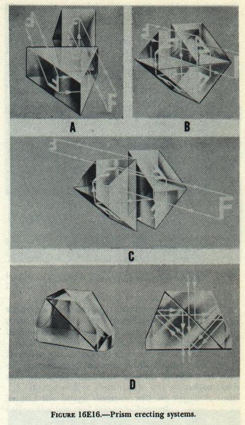
| The real image formed by the objective lens is, of course, inverted. Consequently, the enlarged virtual image seen by the observer in figure 16E15 is also inverted. But if the telescope is to function as a useful fire control instrument, it must present an erect image of the target. The image may be erected in either of two ways. One way is to add an erector lens. The erector lens is used as a second objective, with the first real image as its target. The erector forms a real image of the first real image. Since, after passing through the erector, the image has been inverted twice, the second real image is erect. The ocular then forms an enlarged, erect, virtual image of the second real image. Many telescopes make use of erector lenses. A few telescopes, and most binoculars, use prisms to erect the image. This is accomplished by means of internal reflection at the various prism faces. Figure 16E16 shows several different ways in which prisms may be used to erect an image. (Note that, in part D of the figure, rays strike the two outside surfaces at less than the critical angle; these surfaces are therefore silvered.) To provide a fixed line of sight through a telescope, a reticle may be added. The reticle is a flat piece of glass on one surface of which suitable reference marks, often two lines intersecting at a right angle, have been engraved. The ocular serves as a simple magnifying glass to provide an enlarged virtual image of the reference marks on the reticle. To use the instrument, the observer first adjusts the ocular until he sees a sharp image of the reticle. (If the instrument is a gun-sight telescope, it has been previously adjusted so that the reticle marks lie in the plane of the real image formed by the objective.) The observer will then see a sharp image of the target. with the reticle marks superimposed on it. If the adjustments have been properly made, there will be no relative motion between the target image and reticle image when the observer moves his eye from side to side at the ocular. The observer has, therefore, established a line of sight to the target. 16E8. Correction of aberrations From the foregoing discussion it would appear that a useful gun-sight telescope could be made with only four optical elements: an objective lens, an erector lens, an ocular lens, and a reticle. The actual instruments we use, however, contain a larger number of lenses than this. The additional lenses are necessary to correct the aberrations of the optical system. The surface of a lens is part of a sphere, because spherical surfaces are relatively easy to grind. Lens surfaces of non-spherical curvature are sometimes produced for special instruments, but such lenses are far too expensive to use in mass production. Every lens in a commercial optical instrument therefore has either two spherical surfaces, or one spherical and one plane surface. But light, in passing through a spherical surface, does not behave in an ideal manner. No single lens can actually converge parallel rays to a single point. These departures from ideal performance are called aberrations. Although a number of aberrations must be dealt with in the design of any optical instrument, two examples are sufficient to illustrate the problem. White light is a mixture of colors. As previously stated, the angle of refraction at an optical surface depends on two factors: the angle of incidence and the index of refraction. But the index of refraction of any medium, such as glass, depends on the color of light. Blue light, for example, will be much more strongly bent than red light. (A familiar example of this can be seen in a prism, which will disperse a beam of white sunlight into a spectrum.) A lens will behave in the same way. Blue rays will be bent to a focus closer to the lens than the red rays. Because of this chromatic aberration, a lens will form a separate image for each color, and no two of these images lie in the same plane. As a result, the observer sees a fuzzy, indistinct image. When parallel rays strike a spherical lens surface, those rays nearest the edge of the lens will be bent to a focus nearer the lens than rays striking the lens near its center. This effect is called spherical aberration. Because of spherical aberration, each zone of the lens produces a separate image, and no two of these images lie in the same plane. It is not necessary, in this text, to explain in detail how aberrations are corrected. The optical designer has several variables to work with: the radius of curvature at each surface, the distance between surfaces, and the index of refraction of various kinds of glass. By a suitable manipulation of these variables, the designer is able to make the aberrations of one part of the optical system cancel those of another part, so that the system as a whole can produce an image of useful sharpness. As a result, optical instruments are complex, and the spacing of the various elements must be maintained precisely. In a “simple” telescope, the objective consists of two or three separate lenses, often cemented together. The erector and ocular are each made up of from two to four separate lenses. |