| NAVAL ORDNANCE AND GUNNERY VOLUME 2, FIRE CONTROL CHAPTER 16 RADAR AND OPTICS |
| F. Types of Optical Equipment 16F1. Gun-sight telescopes A gun-sight telescope provides the observer with an enlarged image of the target and thereby makes the target easier to see. At the same time, it establishes a line of sight from gun to target by presenting an image of the reticle crosslines superimposed on the target image. A pair of telescopes is provided at each gun installation. One of these is used by the pointer, the other by the trainer. The trainer controls the train of the mount or turret, and the pointer controls the elevation of the guns, so that the crossline image in both telescopes is superimposed on the target image. Then, provided the axes of the telescopes have been previously adjusted to intersect the axis of the gun at that range, the axis of the gun bore will be aimed directly at the target. However, unless the target is at point-blank range, the gun will not be fired with its axis pointing along the line of sight. The gun must be elevated above the line of sight, because of the curved trajectory of the projectile. The gun must usually be deflected laterally from the line of sight because of wind, projectile drift, and relative motion of gun and target. The necessary elevation and deflection angles are computed by the director. When this information is fed into the sight-adjusting mechanism, the optical axis of the telescope is moved until it diverges from the axis of the gun bore by the required angle. This may be accomplished in any of three ways: by moving the telescope itself, by turning one or more mirrors or prisms inside the telescope, or by a combination of these methods. Then, when the crosslines are superimposed on the target image, the gun will have the deflection and elevation necessary to hit the target. |
| INDEXCHAPTER 16 RADAR AND OPTICS A. Introduction B. Principles of radar C. Types of radar equipment D. Special purpose equipments E. Principles of optics F. Types of optical equipment G. Combat information center (CIC) |
 |
 |
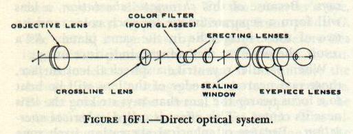
| Turret sight telescopes include all the gun-sight telescopes used in the turrets of battleships, and in the turrets and single-purpose main-battery mounts of cruisers. The optical system may be either of two general types: direct or indirect. Figure 16F1 is a diagram of the direct optical system. The optical axis of the telescope lies along the line of sight, and the sight mechanism provides the elevation and deflection angles by moving the whole telescope. The objective lens forms an inverted real image of the target. This image falls on the engraved surface of the crossline lens, or reticle. Between the reticle and the erecting lenses are the four color filters. (Only three of these are actually colored; the other is plain glass.) These filters are so mounted that the operator can bring any one of them into the line of sight. A filter of the proper color will, under some conditions, increase the contrast of the target image, and decrease the glare from sky and water. The erecting lenses erect the target image, and form a real image of the crosslines superimposed on that of the target. This second real image lies near the eyepiece, or ocular group. The sealing window is of plain glass. It makes it possible to seal the main part of the telescope, to keep out dirt and moisture. The eyepiece may be moved back and forth, to bring the image into focus, without affecting the seal of the rest of the instrument. |
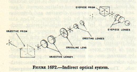
| The indirect optical system, shown in figure 16F2, is basically similar to the direct system. The principal difference is that the line of sight is twice reflected by prisms, so that the axis of the telescope lies at right angles to the line of sight from gun to target. Figure 16F2 shows two separate objective lenses, which together form the first real image. Although this is true in some telescopes, the objective usually consists of two lenses cemented together. The sealing window in this type of telescope is located between the eyepiece prism and the eyepiece lens group. The color filters are usually attached to the eyepiece mount, outside the sealed part of the instrument. A telescope of this type may be mounted with its main axis either vertical or horizontal. When the telescope is horizontal, the sight mechanism controls the deflection angle by rotating the objective prism on a vertical axis. It controls the elevation angle by rotating the whole telescope on its long axis. When the instrument is mounted vertically, these functions are, of course, reversed. Because telescopes with the indirect type of optical system are often mounted vertically, they are usually called turret periscopes. |
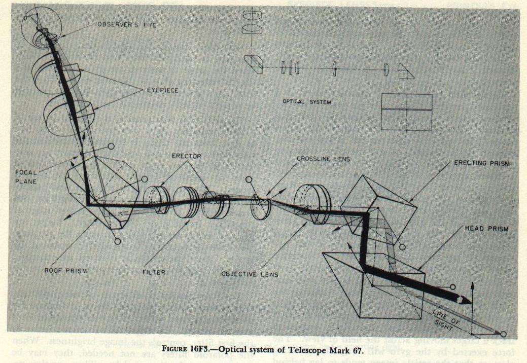 |
| Antiaircraft gun-mount telescopes differ from turret telescopes in that the observer�s line of sight through the eyepiece is not parallel to the line of sight from gun to target. If the target is in the same horizontal plane as the telescope, the observer must look downward into the eyepiece in order to see the target image. This feature makes it easier to track an overhead target without discomfort. Figure 16F3 represents the optical system of a typical antiaircraft gun-mount telescope, the Mark 67. Light from the target is reflected first in the head prism, and then in the erecting prism, before it enters the objective lens. (The erecting prism is misnamed; it is used to bend the line of sight, not to erect the image.) The roof prism turns the line of sight back toward the observer, and at the same time bends it upward through an angle of about 35 degrees. The sight-setting mechanism controls the position of both the head prism and the erecting prism. The head prism rotates on a horizontal axis, to control the elevation of the line of sight. The erecting prism controls deflection of the line of sight by turning on an axis at right angles to that of the head prism. 16F2. Lead-computing sights Lead-computing sights are used with automatic guns to provide a solution to the short-range antiaircraft fire control problem. The sight, like the gun-sight telescope, establishes a line of sight to the target. The gun axis is elevated at the necessary angle above the line of sight when the proper range inputs are made to the sight mechanism. The short-range antiaircraft problem is more complex than the long-range antiaircraft and surface fire control problems. Unless the attacking aircraft is flying directly toward the gun, the elevation and deflection of the line of sight will change rapidly as the target approaches. Because of its high speed, the target may move a considerable distance while the projectile is in flight. The gun must therefore be aimed ahead of the target, if target and projectile are to reach the same point at the same time. In other words, the gun axis must lead the line of sight by the proper angle in both elevation and deflection. The more rapidly the line of sight changes in elevation or deflection, the greater the lead angle must be. As its name implies, the lead-computing sight computes the necessary lead angle. The operator turns and elevates the sight to track the target. When he tracks successfully, the reticle image will appear to be superimposed on the target at all times. The sight, through the gun director, positions the guns so that the gun axis remains parallel to the axis of the sight. The sight mechanism, however, causes the operator�s line of sight to lag behind the axis of the instrument. The more rapidly the sight is moved, the greater this lag will be. Since the operator uses this lagging line of sight to track the target, the axis of the sight, and therefore the axis of the gun, will lead the target by an angle proportional to the rate at which the sight is moved. The lead-computing sight mechanism is based on one or more rapidly spinning gyroscopes. The principles of the gyroscope have been explained elsewhere in this text, in the chapter on torpedoes. It should be remembered that, when the axis of a spinning gyroscope is changed, the gyro will undergo precession, and move its axis in a direction at right angles to that of the applied force. In a torpedo, the gyro is free to move in any direction relative to its mount. In the lead-computing sight, the gyro movement is restrained, either by springs or by an electromagnet. When the sight is turned or elevated, thus tending to change the direction of the gyro axis, the gyro tends to undergo precession. The force it exerts on its restraining mechanism will be proportional to the rate at which the direction of its axis is changed. The sight mechanism applies this force to the optical system of the sight, in such a way that the line of sight lags by the proper angle. |
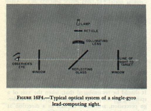 |
| Figure 16F4 represents the optical system of a lead-computing sight using a single gyro. The two windows seal the instrument to keep out dust and moisture. The system does not magnify the target image. The operator observes the target directly, through the two windows and the clear reflecting glass. The lamp at the top of the diagram is used to illuminate the reticle. The reticle is located exactly at the focal point of the collimating lens. Rays of light from the reticle are therefore parallel after they pass through the lens, and after they are reflected toward the operator by the reflecting glass. Because these rays are parallel, the reticle image appears to lie at infinity, and the reticle will not change its apparent direction when the operator moves his head from side to side. |
| The force of precession exerted by the gyro controls the angle of the reflecting glass. Although the angle of this glass has no effect on the line of sight to the target, it determines the apparent position of the recicle. Assume that the sight is trained to track a target moving across the field of view. The force exerted by the gyro will turn the reflecting glass, so that the reticle image tends to lag behind the target. In order to keep the reticle image superimposed on the target, the operator must make the sight axis lead the line of sight to the target. When the sight is elevated to track a target passing overhead, the gyro will tilt the reflecting glass so that the reticle image tends to lag below the target. Again the operator must lead the target in order to track it. Most often, the line of sight to the target will be changing in both deflection and elevation. Then, when the target is tracked, the gyro will turn and tilt the reflecting glass at the same time. Thus the lead angle generated by the sight mechanism will be correct in both magnitude and direction. |
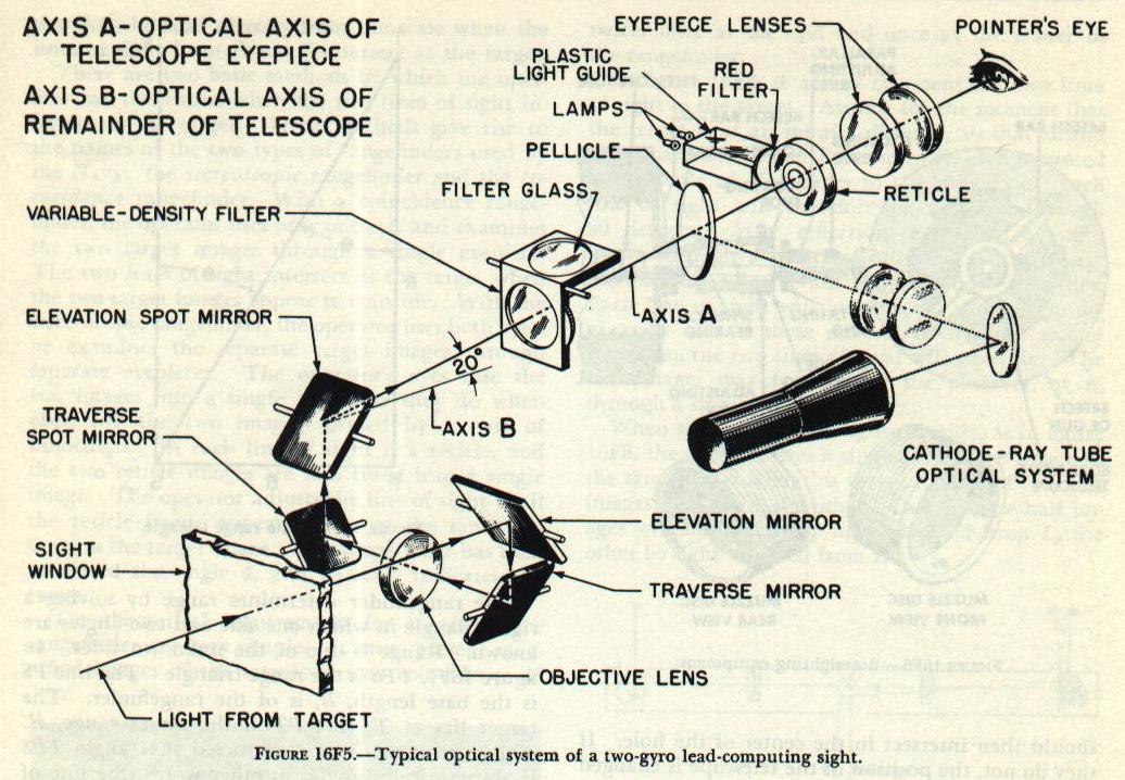 |
| Figure 16F5 is a diagram of the optical system of a lead-computing sight with two gyros. The line of sight from the target is reflected by each of the four mirrors. The two lead-angle mirrors are controlled by the two gyros, so that the optical line of sight lags behind the sight axis when the sight is moved. The two spotting mirrors are used only to adjust the line of sight during boresighting (see article 16F3. The objective forms a real image of the target, in the plane of the reticle. Target image and reticle are examined through the eyepiece. The system provides an enlarged erect image of the target. Since the image is inverted by reflection from the four mirror surfaces, no erector lens is necessary. The filter bracket holds a pair of polaroid filters. One of these is stationary, and serves to decrease the glare from sky and water. The other polaroid filter may be rotated. Its degree of rotation, relative to the first filter, controls the image brightness. When the polaroid filters are not needed, they may be swung out of the line of sight. They are then replaced by a compensating glass, which has the same effect on image position as the two filters. The pellicle is a plastic disc, coated with a thin, semitransparent film of aluminum. It has no effect on the target image, except to decrease its brightness somewhat. The cathode-ray tube is used when the target is tracked by radar, rather than visually. The target �image� formed by the radar appears as a spot on the face of the cathode-ray tube. The light from this spot is reflected by the cathode-ray mirror, and passes through the cathode-ray objective lens. It is then reflected by the aluminum film on the pellicle, back toward the eyepiece. The objective forms an image of the spot in the plane of the reticle. When the axis of the radar antenna is pointed directly at the target, the spot appears to be centered in the reticle. When the target moves off the radar axis, the spot moves toward the side of the tube. The sight operator tracks the target by keeping the spot centered on the reticle. The lead angle generated by the sight controls the angle by which the guns lead the radar axis. |
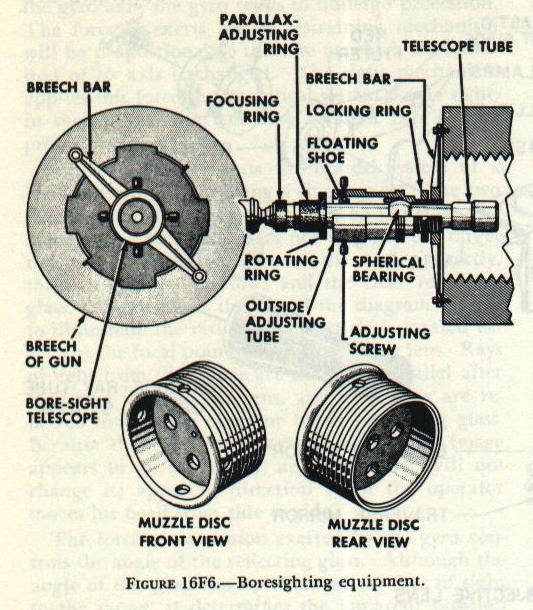 |
| 16F3. Boresight telescope When the sight-setting mechanism is set for zero elevation and zero deflection, the lines of sight through the gun-sight telescopes must intersect the axis of the gun bore at the target. The boresighting operation is used to check this adjustment. One observer is stationed at each telescope, and one at the gun breech. All observers sight on the same target; if the three lines of sight are observed to be on target at the same time, the gun is correctly boresighted. The lines of sight through the telescopes are, of course, established by the crosslines on their reticles. The boresighting equipment provides a line of sight through the gun bore. Boresighting equipment is of several kinds. For the very small guns, such as the 20-mm antiaircraft guns, it consists of a breech attachment containing a peep hole, and a muzzle attachment with cross-lines. The gun axis is aimed at the target by using the peep hole and crosslines as an open sight. The larger case guns may use a boresight with self-contained optics. This equipment converts the whole gun into a telescope. The muzzle fitting contains the objective lens; the breech fitting contains the reticle and eyepiece. The 5�/38 and all bag guns may use a breech bar and boresight telescope. Figure 16F6 shows how this equipment is mounted. The breech bar is secured by screws to two threaded holes in the breech. The telescope housing is screwed into the breech bar, and locked rigidly in place by turning the locking ring up against the breech bar. The telescope is secured in its housing by a spherical bearing and four adjusting screws. |
| The telescope has a simple, straight-line optical system, consisting of objective, reticle erecting lenses, and eyepiece lenses. The position of the objective may be adjusted, to bring the image into focus on the reticle, by turning the parallax-adjusting ring. The muzzle disc fits into the muzzle of the gun; the hole in the center of the disc lies on the axis of the gun bore. To use the telescope, the operator turns the parallax-adjusting ring to bring the hole of the muzzle disc into sharp focus. The crosslines of the reticle should then intersect in the center of the hole. If they do not, the position of the telescope is changed by turning the adjusting screws. When the cross-lines intersect at the center of the muzzle disc, the accuracy of the adjustment may be checked by rotating the telescope on its spherical bearing. The crosslines intersection should remain centered throughout 360 degrees of rotation. The muzzle disc is then removed from the gun, and the objective is adjusted to bring the target image into focus. When the reticle crosslines are superimposed on the target image, the target lies on the axis of the gun. |
| 16F4. Rangefinders The rangefinder consists essentially of a system of optical units assembled in a long, cylindrical tube. The tube is supported by a mount, which permits training the rangefinder on the target. Early forms of mounts were little more than simple tripods. But modern rangefinders are generally supported on mounts integral with turrets or director housings, leaving only the protruding ends exposed. On its forward surface, the tube has a window at each end. Through these windows, the operator establishes two separate lines of sight to the target. |
 |
 |
 |
 |
 |
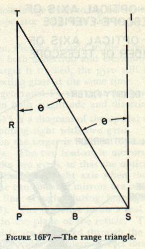
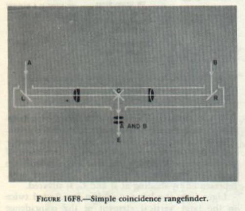
| therefore be read directly from the scale when the lines of sight from P and S intersect at the target. There are two basic methods by which the operator can determine when the two lines of sight intersect at the target. These methods give rise to the names of the two types of rangefinders used by the Navy: the stereoscopic rangefinder and the coincidence rangefinder. With a coincidence rangefinder, the operator uses only one eye, and examines the two target images through a single eyepiece. The two lines of sight intersect at the target when the two target images appear to coincide. With the stereoscopic rangefinder, the operator uses both eyes; he examines the separate target images through separate eyepieces. The operator�s eyes fuse the two images into a single image, as they do when observing the two images formed by a pair of binoculars. In each line of sight is a reticle, and the two reticle images are also fused into a single image. The operator adjusts the line of sight until the reticle image appears to lie at the same distance as the target image. The rangefinder has then measured the angle , and its scale indicates the range. The theoretical requirements for a coincidence rangefinder are very simple. It must present magnified images of the target, so that coincidence of the two images may be accurately established. It therefore uses a telescope in each line of sight. The two lines of sight must point toward the target from the two ends of the rangefinder. They must, however, come together at the center of the instrument, so that both may be seen by a single observer. Each line of sight is therefore reflected twice: once at the end and once at the center of the rangefinder. In figure l6F8, A and B represent the two lines of sight to the target. Assume for the moment that the target is at an infinite distance, so that A and B are parallel. L and R are mirrors, each mounted at an angle of 45 degrees to the tube axis. Each line of sight will therefore be reflected through 90 degrees. After reflection, each line of sight passes through a telescope objective lens. C represents two 45-degree mirrors, one above the other. Each line of sight will be reflected through 90 degrees by one of these mirrors. After the second reflection, the two lines of sight will coincide. The two images may be seen by the observer, at E, through a single eyepiece. When the two lines of sight coincide, as in figure l6F8, the observer sees a single, unbroken image of the target. Actually, this image consists of two half images, one above the other. One of these half images will be formed by light reflected from L, the other by light reflected from R. Part A of figure 16F9 shows a slight improvement on the optical system of figure 16F8. The two mirrors at L and R have been replaced by pentaprisms. In these prisms, the line of sight is reflected twice. �The images are therefore not reversed from left to right, as they would be by single mirrors. The pentaprisms cannot depend on total internal reflection, since light strikes both reflecting surfaces at less than the critical angle; these surfaces are therefore silvered. Pentaprisms are used only in relatively small rangefinders. The largest rangefinders in service would require pentaprisms of prohibitive size. In these instruments, two mirrors are substituted for each pentaprism, with their surfaces in the same relative position as the two reflecting surfaces of the pentaprism. |
| If the target is not at infinity, the two lines of sight will not be parallel, and they will not coincide at E. (For simplicity, the eyepiece has been omitted in figure 16F9.) The broken line B� represents the line of sight from a target at medium range. This line diverges from B by the angle of convergence, u. The target image, as seen by the observer, will be broken in the center by a horizontal line; the upper half of the image will be displaced with respect to the lower. (The observer customarily ranges on some vertical line on the target, so that any displacement of the upper image can be easily detected.) The operator can measure the angle of convergence, and therefore the range, by turning the line of sight B� through the angle There are several ways in which this could be done; for example, by rotating the pentaprism at R on a vertical axis. This system, however, has an obvious disadvantage. The angle of convergence is always very small. Assume, for example, that the base length of the rangefinder is 20 feet. If the target range changes from 1,000 yards to 50,000 yards, the angle of convergence will change by approximately half of one degree. If the pentaprism is rotated, it will deviate the line of sight by twice the angle of rotation. The rangefinder would be changed from minimum to maximum range by only one quarter of a degree of adjustment. Even with reduction gearing between the range scale and the prism, the scale would be too crowded to be useful. Part B of figure 16F9 represents the system actually used. Two thin prisms or wedges, comprising the compensator, have been inserted in the B� line of sight. A prism, it will be remembered, deviates light toward its base. If the two wedges deviate B� through the angle of convergence, the two lines of sight will then coincide, and the target image will appear unbroken. The compensator is so constructed that the angle of deviation is continuously variable. This is accomplished by rotating the two wedges through equal angles, in opposite directions. Figure 16F10 shows how this system works. If it is remembered that a prism always deviates light toward its base, the figure is self-explanatory. As the diagrams show, the wedges must be rotated through an angle of 90 degrees to change the deviation from minimum to maximum. This makes possible the use of a long, un-crowded range scale. The optical system of an actual rangefinder is somewhat more complex than that shown in figure 16F8, although it will not be described in detail here. The rangefinder includes a supplementary optical system for use in calibration. It also has a halving adjustment, by which the two images can be adjusted so that there is no overlapping or duplication. The astigmatjzer, which may be inserted in the lint of sight when necessary, distorts the image so that the image of a point appears as a vertical line. This makes it possible to use a coincidence rangefinder to range on a searchlight at night. And the rangefinder does not use two simple mirrors to reflect the images toward the observer, as shown at C in figures 16F8 and 16F9. It uses a coincidence prism for this purpose. |
 |
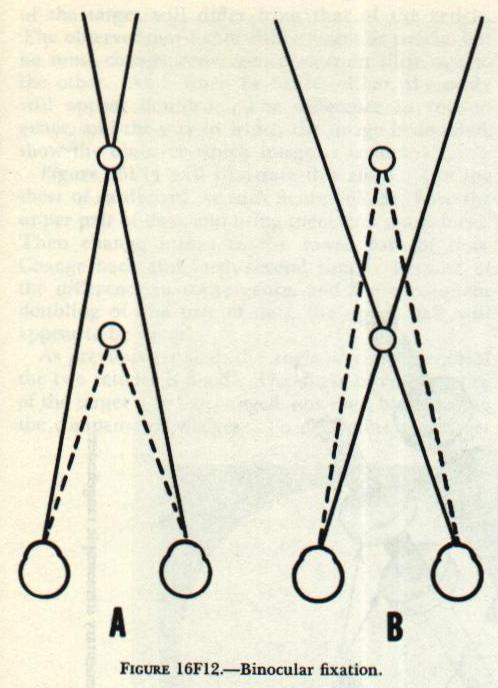
| Figure l6Fl1 is a simplified diagram of a coincidence rangefinder, showing the coincidence prism. This prism is rather complex, and difficult to represent in a two-dimensional drawing. It consists of three separate prisms. The two larger prisms are cemented together. Half of the cemented area, represented by shading at B and C, is silvered. Light from the left pentaprism is reflected twice in the large vertical element of the coincidence prism group. Half of this light-the part that forms the lower half of the image-then strikes the silvered surface and. is reflected toward the single reflecting prism. The rest, forming the upper half of the image, misses the silvered surface; it passes out through the top of the prism, and is discarded. Light from the right pentaprism, after deviation by the compensator wedges, is reflected upward at the lower face of the diagonal prism. It is reflected again at the roof-shaped upper faces. The part of this light that forms the lower half of the image strikes the silvered surface, where it is reflected upward and discarded. The rest, forming the upper half of the image, continues on to the single reflecting prism. The single reflecting prism reflects both halves of the image toward the eyepiece. The coincidence prism group reflects each half of the image without reversing it from left to right, as single mirrors or prisms would. In addition, it inverts the image. Therefore no erector lens is needed in a coincidence rangefinder. The use of a stereoscopic rangefinder depends on the stereoscopic vision of the operator. �Stereoscopy� has the literal meaning of its Greek roots: seeing solid. Stereoscopic vision makes it possible to see objects as solid and three-dimensional, and to judge their relative distances. The appearance of solidity has no application in rangefinding. Operation of the stereoscopic rangefinder depends on judgment of relative distances. The relative distance of two objects may be determined in any of several ways: 1. Intervening objects. When one object partially conceals another, the concealed object is obviously the more distant. 2. Relative sizes. If two objects known to be of equal size are at different distances from the eye, the more distant object will appear smaller. S. Aerial perspective. The veiling effect of atmospheric haze usually increases with distance. If one of two objects appears hazier than the other, it is probably the more distant. 4. Focusing. The muscular effort required to focus the eye depends to some extent on the distance of the object focused on. This effect is useful only at short distances. 5. Convergence. If an object is to be seen sharply by both eyes, the two lines of sight, one from each eye, must intersect at the object. The angle of convergence depends on the distance of the object. A certain muscular effort is required to change the angle of convergence. This effort provides the observer with a basis for judging relative distances. 6. Image doubling. When the two lines of sight intersect at a given object, all objects nearer or farther will appear doubled. It will be shown be1ow that nearer objects appear doubled in one way; farther objects appear doubled in an entirely different way. Of the effects listed above, the first four are apparent even when one eye is closed. They are therefore not suitable for use in a stereoscopic rangefinder. The last two, however, require binocular vision-the use of both eyes at once. The stereoscopic rangefinder makes use of both these effects. The human eye is a simple optical instrument. Refraction occurs at the cornea, or curved front surface of the eye, and at both surfaces of the lens, located a short distance behind the cornea. The lens and cornea, acting together, form a convergent lens system. They form a real inverted image of any object seen. This image falls on a sensitive layer, the retina, at the back of the eye. The nerves of the retina, when stimulated by light, carry impulses to the brain, where the image is interpreted. One small spot on the retina is capable of perceiving a sharp image; the image on any other part of the retina is more or less blurred. The outward projection of this spot, through the optical center of the lens, is the line of sight. To see any point clearly with one eye, the observer must fixate that point. Fixation consists in turning the eye until the line of sight reaches the point observed; the image of that point then falls on the small sensitive spot of the retina. Binocular fixation of a point requires that the two lines of sight intersect at the point of fixation. Each eye then forms an image of that point on the sensitive spot. The small size of this spot may be demonstrated by fixation of a colon (:). Either dot of the colon may be fixated separately; shifting from one to the other requires a detectable muscular effort. In judging the relative distance of two nearby objects, the observer customarily uses his two eyes as a simple coincidence rangefinder. The lines of sight from the two eyes correspond to the lines of sight from the two end windows of the rangefinder. The distance between the eyes corresponds to the rangefinder base length. When the two rangefinder images coincide, the range may be read on the scale; when the two eye images coincide, the distance may be estimated from the muscular effort required to secure coincidence. To demonstrate this effect, hold the index finger of one hand vertically, at arm�s length in front of the face. Hold the index finger of the other hand vertically in front of the face, at a shorter distance. Now shift fixation from one finger to the other, and note the muscular effort required to change the angle of convergence. Note also that when either finger is fixated, the other appears doubled. When one finger is fixated, the fact that the other appears doubled shows that it lies at a different distance; the way in which it is doubled shows whether it is nearer or farther than the one fixated. Figure 16F12 illustrates this point. PAGE 38 |
 |
 |
 |
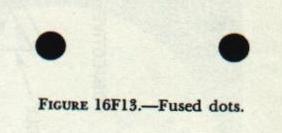
| In both drawings, the solid lines represent the lines of sight to the point of fixation. The broken lines represent the path of light from the other finger to the eyes. In part A of the figure, the point of fixation is on the more distant finger; the other finger appears doubled. To the right eye, the near finger will appear to be at the left of the point of fixation. To the left eye, it will appear to be to the right. In part B of the figure, the near finger is the point of fixation. Now the right eye sees the other finger on the right, while the left eye sees it on the left of the point of fixation. Because the manner of image doubling differs, it is possible, by fixating either finger, to judge which is the closer. By changing the fixation from one to the other, and thereby changing the angle of convergence, the original judgment may be confirmed. However, the ability to judge relative distances is limited. If both objects are beyond the radius of stereoscopic vision-approximately 450 yards-the difference between their angles of convergence is too small to be detected. This distance is obviously too small to be useful in finding the range of a target. The stereoscopic rangefinder extends the observer�s radius of stereoscopic vision by increasing the apparent angle of convergence of distant objects. It does this in two ways: first, it provides magnified images of the target; second, it increases the effective distance between the observer�s eyes. The stereoscopic rangefinder, like the coincidence type, uses two telescopes, with their lines of sight extending toward the target from the two end windows. The telescopes provide magnified images of the target. And the effective distance between the observer�s eyes is equal to the base length of the rangefinder. The observer�s eyes fuse the two target images, one from each telescope, into a single unbroken image, just as they do when observing the target through a pair of binoculars. In each telescope of the rangefinder is a reticle. The observer fuses the two reticle images into a single image. Figure 16F13 provides a simple exercise to show how this is possible. Hold a sheet of cardboard on edge, perpendicular to the paper, midway between the two dots. Place the head about 12 inches from the page, so that the eyes can look squarely at the paper as in reading. Adjust the cardboard so that each eye sees only one of the dots. Now, while looking at the dots, relax the eyes and try to look through the paper. After a short time the two dots will fuse into a single, blurred image. Without losing fusion, refocus the eyes until the two dots appear as a single, sharp image. This exercise is well worth while, even if it requires several minutes of patient effort. Because the apparent angle of convergence of the two reticles is fixed, the reticle pattern appears to lie at a certain fixed distance in space. If the target happens to be at that distance, target and reticle will appear to be equally distant from the observer. Assume for a moment that the target is at some other distance. The apparent angle of convergence of the target will differ from that of the reticle. The observer may fixate either target or reticle, but he must change convergence to from shift one to the other. And, when he fixates either, the other will appear doubled. The difference in convergence, and the way in which the image is doubled, show the observer which image is nearer. |
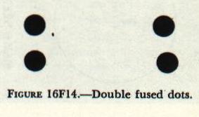
| Figure 16F14 will illustrate this effect. Use the sheet of cardboard, as with figure l6F13. Fuse the upper pair of dots, and bring them into sharp focus. Then change fusion to the lower pair of dots. Change back and forth several times. Because of the difference in convergence, and the consequent doubling of one pair of dots, the upper pair will appear to be closer. As previously stated, the angle of convergence of the two reticles is fixed. The angle of convergence of the target may be changed, however, by adjusting the compensator wedges. To determine the target range, the operator adjusts the wedges until the target and reticle appear to lie at the same distance. He may then read the range on the calibrated scale. |
 |
 |
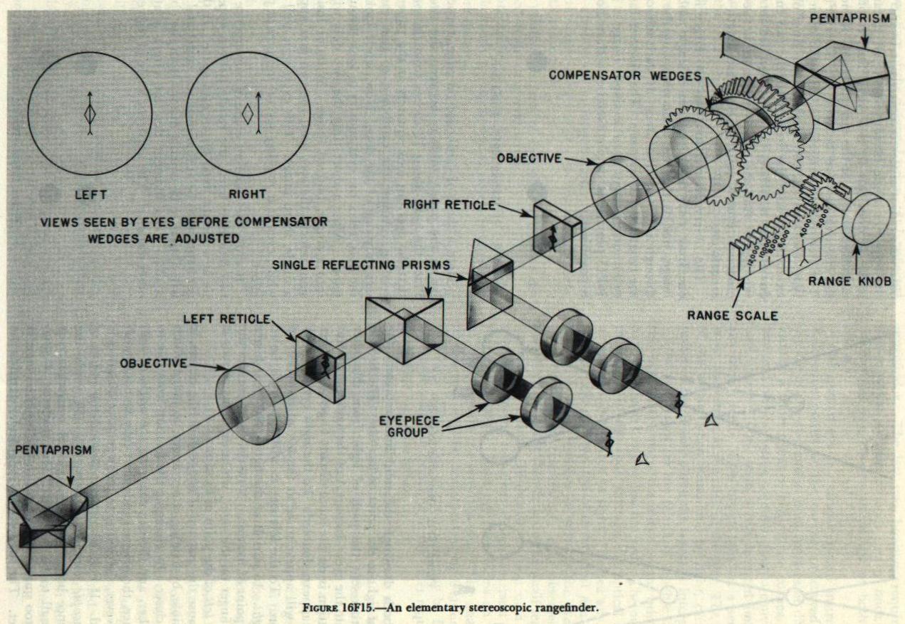
| Figure l6Fl5 is a simplified diagram of the optical system of a stereoscopic rangefinder. (Each of the two telescopes contains an erector system, which has been omitted from the drawing for the sake of simplicity.) The two circles at the upper left show the views seen by the two eyes before adjustment of the compensator wedges. The diamonds represent the reticle pattern; the arrows represent the two images of the target. By using a piece of cardboard, it is possible to fuse these two views, although this takes more effort than fusing the dots in figure 16F14. The target arrow will appear to be considerably more distant than the reticle diamonds. |
| Figure 16F16 represents the image of reticles and target as actually seen through the eyepiece group. Note that the reticle image consists of one row of diamonds and four rows of vertical lines. The center diamond is used for ranging on the target. All the marks in any one row appear to be at the same distance from the observer. The row of lines immediately above the diamonds appears to be more distant than the diamonds, and the top row appears to be still more distant. The row immediately under the diamonds appears to be nearer than the diamonds, and the bottom row appears to be nearer still. When the center diamond has been superimposed on the target, the rows of vertical lines make it possible to estimate the range of bursts or splashes without readjusting the compensator wedges. At any given range, the apparent distance between any two adjacent rows corresponds to a fixed distance. When this distance has been determined from a table, the necessary spot corrections can be quickly estimated. The horizontal distance between any two adjacent marks in the same row correspond to five mils in deflection. Thus deflection spots can be made without training the rangefinder off the target. Because it is more useful for spotting, as well as for ranging on fast-moving targets such as aircraft, the stereoscopic rangefinder is more widely used than the coincidence rangefinder. |