| NAVAL ORDNANCE AND GUNNERY VOLUME 2, FIRE CONTROL CHAPTER 19 SURFACE FIRE CONTROL PROBLEM |
| HOME INDEX Chapter 19 SURFACE FIRE CONTROL PROBLEM A. General B. Analytical solution C. Graphic rangekeeping D. Mechanical solution-general E. Basic mechanisms F. Mechanical solution-basic rangekeepers G. Mechanical solution-establishing the horizontal plane |
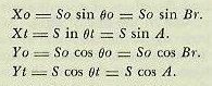
| B. Analytical Solution* *See also chapter 17. 19B1. Steps in solving the fire control problem The solution of the problem is to be considered in five steps: 1. Establishing present target position. 2. Computing necessary offset from the line of sight. 3. Correcting for the effects of deck inclination. 4. Computing gun orders. 5. Correcting the fall of shot. 19B2. Establishing present target position The first step in the solution of the problem is to establish the line of sight to the target by radar or optical instruments. Accurate measurements are essential for the following: 1. Present range (R). The observed distance from ship to target, measured along the line of sight. This quantity is determined by rangefinder, by fire control radar, or if no better method is available, by estimate. 2. Relative target bearing (Br). The angle between the vertical plane through the fore-and-aft axis of own ship and the vertical plane through the line of sight, measured in a horizontal plane clockwise from the bow. Most of the computing devices used for solution of the surface problem assume that own ship and target are in the same horizontal plane. Most gun directors used with these computers, because of structural considerations, are trained in a plane parallel to the ship’s deck, so of necessity measure target bearing in this plane. Target bearing measured in the plane of the deck (B’r’, called director train) is converted to the horizontal plane by a computed correction, jB’r’, called deck-tilt correction, to become Br. B’r' is measured with director sights or fire control radar. If ship and target were stationary, the only corrections necessary would be those for wind and for the ballistics of the gun. However, the practical difficulty of the solution is increased by the need for computing and applying corrections for relative motion of own ship and target, and for deck inclination with respect to the horizontal. 19B3. Relative target motion When ship and target are moving with respect to each other, gunfire, to be accurate, must compensate for the error caused by their relative motion during the time of flight of the projectile. An appreciable time interval elapses while the projectile is in the air. This time is significant when it is considered that a ship at 30 knots is actually traveling 16.89 yards per second. The method employed analyzes the relative motion of own ship and target to determine the rates at which range and bearing are changing, computes the amount of change during any desired time interval, and applies this change to the original measured quantity to produce continuously accurate values of the coordinates of present target position. The same rates, multiplied by the time of flight, compute the predicted change in target position during the time of flight. This procedure may be compared to the working of a clock, which, once set correctly and being so constructed that it measures the rate of the passage of time, can add increments of time to the original setting and supply us with the correct time at any later instant. 19B4. Components of relative target motion The apparent motion of the target as seen from the deck of own ship is the resultant of the motion of both vessels. To take a simple case, if both ships are steaming down the line of sight toward each other, each at the rate of 30 knots, it is apparent that the range is closing at the rate of 60 knots. Since this is true, the component of relative target motion affecting range can be obtained by combining the range component of own-ship motion with the range component of target motion. The deflection component can be similarly handled. In the chapter on exterior ballistics, the line-of-sight diagram was presented, with own-ship and target motion represented by vectors. The length of the vector represents speed, while the direction of the vector indicates course. The vectors were resolved into their components in and across the LOS. These components are: Symbol Definition Yo Range component of own-ship velocity. The horizontal component of own-ship velocity along the line of sight. Yt Range component of target velocity. The horizontal component of target velocity along the LOS. Xo Lateral component of own-ship velocity. The horizontal component of own-ship velocity across the LOS. Xt Lateral component of target velocity. The horizontal component of target velocity. across the LOS. These components can be combined to provide range and bearing rates: Symbol Definition dR Range rate. The time rate of change of range. The component of relative target motion along the LOS. dR = Yo + Yt. RdBs Linear bearing rate measured at the target. The component of relative target motion across the LOS. RdBs = Xo + Xt. dBs Angular bearing rate. The time rate of change of target bearing. dBs=K x RdBs/R. K Constant. These components are illustrated in figure l9Bl. The line-of-sight diagram is used to derive the components of own-ship and target motion. It is evident that: |
 |
 |
| The direction of the effect of the components on range or bearing can best be ascertained by observation. Consider the target stationary; then examine the direction of Yo and Xo. If, as in figure l9Bl, Yo causes range to increase, it is considered positive. Xo, the bearing component, is positive if, as in the figure, it causes the line of sight to move to the right (or the numerical value of bearing to increase). Then consider own ship to be motionless, and assign algebraic signs to target components by the same reasoning. In figure 19B1, by inspection, Yo and Xo are positive and Yt and Xt negative. 19B5. Range rate In figure l9Bl (c), the range components have been added algebraically to form the range rate. Since Yt is greater than Yo and is negative, dR is negative, decreasing the range. Range rate must be converted from knots into yards per second, since range is measured in yards. The conversion constant is the result of the following equation: 1 knot =2,027 yards per hour/3,600 seconds per hour=0.563 yards per second. 19B6. Bearing rate In figure l9Bl (b), the bearing components are added to obtain the linear bearing rate RdBs. Since Xo is positive and larger, RdBs is positive (increasing). Since bearing is an angle, rate of change of bearing must be converted to an angular rate. RdBs is linear. The conversion is accomplished as follows: 1 knot = 0.563 yards per second. 1 yard per second = 1/R (yds)/1000 = 1000/R (yds) mils per second. 1 mil = 3.438 minutes of arc. 1 knot at range R (yds) = 0.563 X 1000/R (yds) X 3.438 = 1936/R (yds) minutes of arc per second. Therefore, dBs (min. of arc per sec.) = 1936 x RdBs (kts)/R (yds) |
| 19B7. Use of range and bearing rate Range and bearing are computed continuously by applying the rates derived in the preceding paragraphs. Additional definitions which are necessary include: |
 |
| By continuously applying the rates it is possible to keep accurate values of present range and bearing, even though measurements of range and bearing may be interrupted. And by using time of flight, it is possible to predict the position of the target at the end of the time of flight, assuming that relative motion is constant for the short time interval involved. In practice, the error resulting from the fact that RdBs is a linear instead of an angular rate is reduced in modern computing instruments by using very short time intervals in the computation. Also for obtaining each successive instantaneous value of R and Br the new values of dR and RdBs obtained for the preceding instant are used. This completes the analytical solution of the problem of maintaining continuous values of present and predicted range and bearing. It is immediately apparent that because of the time required for computation, the large number of calculations necessary, and the errors introduced by using finite time intervals, the analytical solution is of no practical value in modern gunnery. Mechanical and electrical rangekeepers and computers have been perfected which accomplish all the steps of the computation automatically on the basis of accurate basic inputs. |
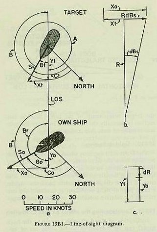
 |
| 19B8. Computing bore offsets The angles by which the gun bore must be offset from the line of sight in order to hit the target are sight angle (Vs) in elevation and sight deflection (Ds) in train. Figure 19B2. 19B9. Sight angle The chapter on exterior ballistics presented the method of determining the vertical angle by which the bore axis of the gun must be offset from the line of sight. This angle is made up of the standard angle of elevation (column 2 of the range table), plus the angular equivalent of the total ballistic correction in range, plus the angular equivalent of range spots. In fire control, this angle is called sight angle (Vs). It should be noted that one of the largest components of the range ballistic correction is normally the correction in range for relative motion of own ship and target. 19B10. Sight deflection The horizontal angle by which the bore axis must be offset from the LOS is the angular equivalent of the total ballistic in deflection plus any deflection spots. The details of this computation were also covered in the chapter on exterior ballistics. Again, a large part of sight deflection is normally the correction for relative motion of own ship and target. 19B11. Counteracting the effects of deck inclination Inclination of the deck with respect to the horizontal can be considered to be made up of two components, one in the plane through the line of sight, the other in a plane perpendicular to this plane through the line of sight. The first is relatively easy to counteract, since it affects only gun elevation. By keeping the line of sight on the target as the deck moves, the gun axis is maintained in its proper position. The deck inclination across the line of sight is more difficult to counteract. |
 |
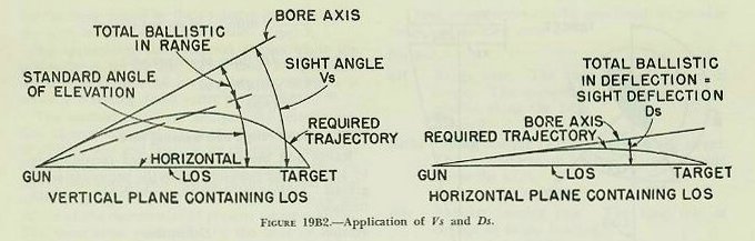
| 19B12. Trunnion tilt Inclination of the deck across the line of sight tilts the gun trunnions out of the horizontal. For the purpose of simple explanation, the entire gun mount is considered to rotate around the line of sight. Figure l9B3 illustrates the effect of this motion. As one looks along the LOS, the gun trunnions are seen to be tilted to the right, swinging the elevated gun barrel to the right. It is apparent that this will cause a deflection error to the right, if not corrected. The same movement decreases the amount the gun bore is elevated above the horizontal, introducing a range error. What actually has happened is that the sight angle and sight deflection computed for the vertical and horizontal planes respectively are now being applied in two entirely different planes; i. e., in planes perpendicular to and parallel to the deck plane, which is now inclined. To take the extreme case, a trunnion tilt of 90 degrees would result in the bore axis being offset horizontally by the amount of Vs and vertically by the amount of Ds. The deflection error resulting from trunnion tilt is normally large and in the direction of the tilt. The range error is small and almost always causes a decrease in gun range. An examination of figure 19B3 shows also that the angular displacement of the gun barrel depends upon the amount of gun elevation and the amount of trunnion tilt. 19B13. Correction for trunnion tilt Even though trunnion-tilt errors are shown in the vertical and horizontal planes, the gun is limited in its movement to training in the deck plane and elevating in a plane perpendicular to the deck. Consequently, the corrections must be calculated in the deck and perpendicular planes. As the deck is tilted, the gun barrel describes the surface of a cone the axis of which is the LOS. To return the barrel to a position parallel with its former position in space, the mount must be trained in the deck plane, which is now inclined, and elevated or depressed in a plane perpendicular to the deck. As the mount is trained, the gun barrel will follow the surface of a cone the axis of which is perpendicular to the deck. |
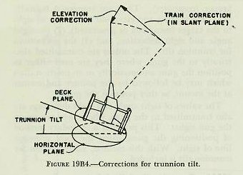 |
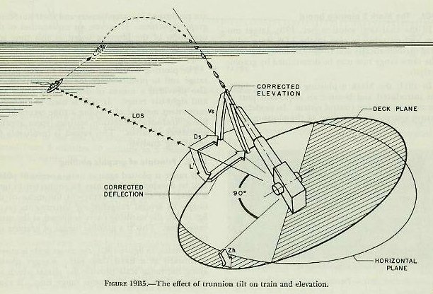
| Figure 19B4 shows the necessary corrections. Applying the required correction by training left is training “uphill,” so that the bore axis would actually move above its original position. Therefore, it is necessary to depress the gun. It is evident that errors resulting from trunnion tilt cannot be corrected by applying equal and opposite amounts of gun train and elevation. Rather, it is necessary to compute the amount of movement in and perpendicular to the deck plane. The mathematical solution of this problem is involved, and will not be included in this text. However, figure 19B5 shows how trunnion tilt corrections ensure that the gun will be offset from the LOS by Vs and Ds when the deck is inclined. The only practicable method of correction for trunnion tilt is by mechanical means, which will be discussed later. |
 |
| 19B14. Computation of gun orders In modern gunnery, the gun battery is positioned to hit the target by training the guns to a certain angle relative to the fore-and-aft axis of the ship, and elevating them to a certain angle relative to the reference (deck) plane. These angles are known as gun train order and gun elevation order. Gun orders are computed mechanically in the range-keeper (computer). They are composed basically of (1) the bearing and elevation of the line of sight to the target (measured or generated), (2) the sight angle and sight deflection, and (3) the corrections for trunnion tilt. The orders are transmitted electrically to the guns, where they are used either to position the guns automatically or to position dials which may be followed by the pointer and trainer at the mount, as they position the guns. The values of sight angle and sight deflection are also transmitted to the guns, where they are set on the gun sights. This provides a secondary method of positioning the guns, using the local telescope line of sight. With this method, no correction for trunnion tilt is included. 19B15. Correcting the fall of shot Regardless of the accuracy of all computations, an error in the fall of shot may still exist. For example, information on which the calculations are based may not be completely accurate. These errors must be corrected by spotting the salvos to the target. The methods of spotting have been covered in the preceding chapter. |