US NAVY
FIRE CONTROL PAGES
NAVAL ORDNANCE AND GUNNERY
VOLUME 2, FIRE CONTROL
CHAPTER 25
LINEAR-RATE ANTIAIRCRAFT
FIRE CONTROL SYSTEMS
Chapter 25 Linear-rate antiaircraft fire control systems
A. General description
B. Director
C. Computer
D. Mark 6 stable element
25A1. Introduction
Antiaircraft fire control systems of various types are designed to control guns ranging in size from light machine guns through 8”/55 rapid-fire guns. For convenience, these systems will be considered in two classes: those which determine rates of change of relative target motion as linear rates (linear-rate systems), and those which measure the angular velocity of the line of sight by gyroscopic means (relative-rate) systems, described in chapter 26.
The Gun Fire Control System Mark 37 is the most significant example of the linear-rate system. It is installed on destroyers, cruisers, carriers, battleships, and some types of large auxiliaries. It is the primary means of control of the 5”/38, 5”/54, and 6”/47 guns for both surface and antiaircraft fire; it may be used, with appropriate cross connections, to control heavy machine-gun mounts, or major-caliber surface-type guns in special uses. The Computer Mark lA, which normally is a component of the Mark 37 system, is also used as a part of the Gun Fire Control System Mark 54 for the control of 8”/55 guns on cruisers of the Salem class.
The discussion in this chapter, unless otherwise stated, is limited to the modifications of the system designed to control the 5”/38 gun. For details of other modifications, as well as for specific instructions regarding adjustments, repairs, tests, and the like, the student is referred to appropriate publications of the Bureau of Ordnance, while appropriate OpNav and Fleet training publications must be consulted for operational doctrine.
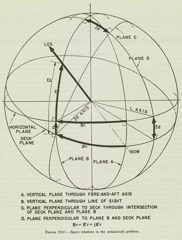
25A2. Principles
The Gun Fire Control System Mark 37 is similar in many respects to the main-battery systems described in chapter 20. All elements of the systems are referred to a common reference system, with mechanical provisions for correcting the solution for the effects of roller-path inclination and parallax. Inclination of the deck plane from the horizontal is measured and compensated for by a gyroscopic stable element.
The primary functions of the system are to provide:
1. Continuous automatic gun positioning.
2. Continuous automatic fuze setting.
3. Continuous sight-angle and sight-deflection indication at the guns.
4. Continuous-aim, selected-level, and selected crosslevel fire.
5. Star-shell fire control.
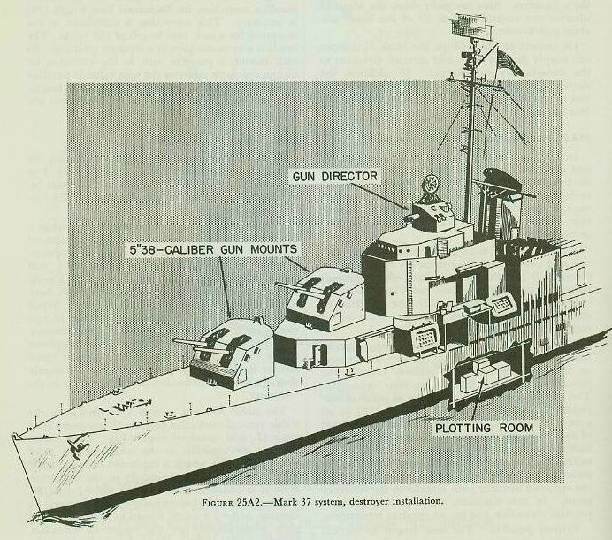
A complete system consists of three major units: a Mark 37 director, with a radar, a Mark 6 stable element, and a Mark 1A computer, with the associated instruments at the gun.
Destroyers and large auxiliaries carry one complete system. See figure 25A2. Cruisers and carriers have two systems, while battleships have four.
Directors are installed high in the ship’s structure, while stable elements and computers are installed below decks in protected plotting rooms. All elements are connected by a synchro transmission system, and are tied into this transmission system at one or more switchboards located in the plotting rooms.
Some battleships have two separate plotting rooms, each containing two computers and two stable elements. Some large carriers have two plotting rooms, each with one computer/stable-element installation. Cruisers and the other carriers have one AA plotting room with two such installations. All other ships equipped with a Mark 37 system have one plotting room, with one computer and one stable element.
Normally, each director in a multiple installation controls a designated group of guns and is connected to a designated computer. However, switching arrangements permit any director to control any or all guns and to be connected to any one of the computers. Also, on many ships, the Mark 37 director can control part or all of the heavy machine-gun battery.
On cruisers and battleships, the Mark 37 director can supply director train and director elevation to the main-battery rangekeeper. In addition, the three major units of the Mark 37 system can control the main battery in AA fire, using pre-selected fuze settings.
25A4. Parallax and roller-path corrections
In order to obtain maximum flexibility, all train and elevation orders and measurements are based on a common reference system. Range errors due to horizontal distances between units of the system are not considered. However, roller-path inclination, horizontal parallax, and vertical parallax are accounted for.
Roller-path inclination. A roller-path tilt corrector or compensator to correct for roller-path inclination is installed at each gun. On ships with more than one director, each has a roller-path tilt corrector. When there is only one director, its roller path is the reference plane and it has no tilt corrector.
Horizontal parallax. The reference point in train is usually at the director, if there is only one; or, if more than one, then midway between the forward and after directors on their centerline. The computer transmits the value of parallax correction for a 100-yard horizontal base (Ph) to all guns and directors. In the train indicator-regulator of each unit, this parallax correction for 100 yards base is converted (by a simple gear ratio) to correction for the unit’s actual distance from the reference point. Where only one director is installed, the center of its roller path is taken as the reference point. In this situation, the director needs no parallax correction and has no parallax mechanism.
Vertical parallax. The base length or vertical parallax is the distance between the director telescopes and the mean gun-trunnion height. Individual trunnion-height variations from the mean are small enough to neglect. In multiple installations, telescope-height variations between directors are also neglected. A unit vertical base length, usually 30 feet, is used. Parallax (Fe) based on this 30-feet height is calculated in the computer and sent to the guns as part of gun elevation order.
Hence, no special vertical parallax mechanism at the mounts is needed.
A special case exists on large carriers such as the Essex and the Midway classes. On these ships, horizontal distances are so great that a vertical parallax correction for horizontal base length (Pu) is necessary. This correction is calculated in the computer for a unit base length of 100 yards. The result is sent to the guns as a separate quantity. At each mount, a parallax unit in the elevation indicator-regulator converts the unit value of parallax to the proper amount for the actual base length. The resulting correction is applied to the gun elevation response.
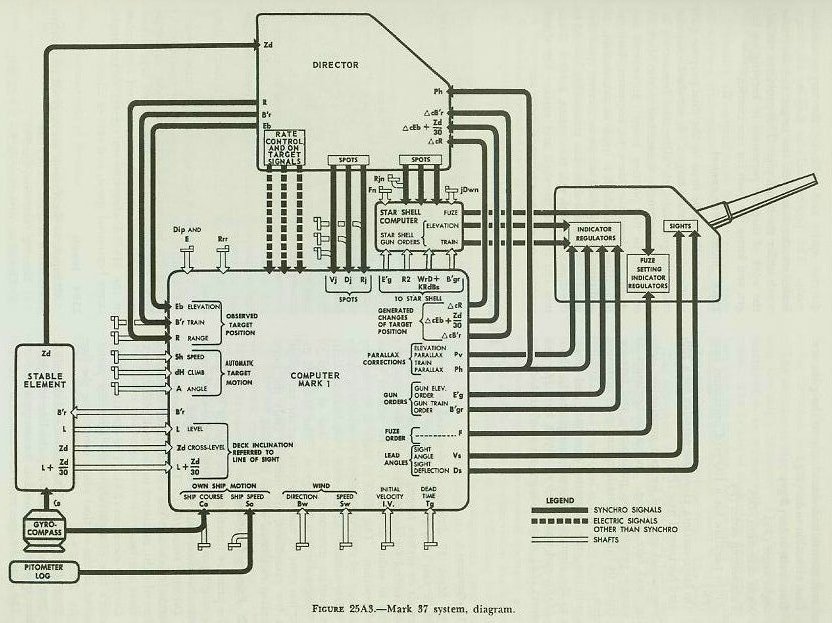
Figure 25A3 is a schematic diagram showing the principal interconnections of a single Gun Fire Control System Mark 37. All electrical circuits between units of the system pass through the fire control switchboard.
The director, in addition to telescopes, carries a rangefinder and radar equipment. This equipment is used to measure and transmit to the computer: director elevation (Eb), director train (B’r), and present range (R). The control officer in the director may estimate target angle (A), target horizontal speed (Sh) and rate of climb (dH). When the computer is in the automatic method of rate control, it is not necessary to make these estimates. The control officer sends these values by telephone to the computer operators. Hand-operated transmitters in the director provide electrical transmission of elevation, deflection, and range spots to the computer.
The stable element, a unit very similar to the stable vertical studied in chapter 20, measures level angle (L) and crosslevel angle (Zd). These values are sent mechanically to the computer. A third value, L + Zd/30, which is explained fully in article 25Bl4, is also sent mechanically to the computer. Here it is added to increments cE, forming increments cE+L+Zd/30, which is transmitted electrically to the director. In director, increments cE+L+Zd/30 is used to keep the line of sight automatically on the target in elevation. Crosslevel (Zd) is transmitted electrically from the stable element to the director to stabilize the optics and radar antennas in crosslevel.
Electrical inputs to the computer come from the director, the ship’s gyro compass, and the pitometer log (speed). As explained above, inputs to the computer from the stable element are mechanical. Finally, the computer operators apply various manual inputs to the instruments. The quantities computed and transmitted electrically to the guns are:
1. Gun elevation order (E’g).
2. Gun train order (B’gr).
3. Sight angle (Vs).
4. Sight deflection (Ds).
5. Fuze setting order (F).
6. Train parallax for a 100-yard horizontal base (Ph).
7. On large carriers, elevation parallax for a 100-yard horizontal base (Pv).
These values are used for gun positioning, sight setting, and fuze setting. Indicator-regulators at the mounts provide gun positioning and fuze-setting either by fully automatic means or by matching pointers.
In addition, the computer generates and transmits to the director changes in range (increments cR), elevation (increments cE), and train (increments cB’r). With level (L) and crosslevel (Zd), these changes are used to hold the director optics and radar on the target continuously. This process includes keeping the range-finder wander marks on the target and the radar notch under the target pip. This provision reduces the work of director personnel in keeping on target, and forms the basis for rate control.
25A6. Illumination control
Star shells can be fired by the dual-purpose guns to illuminate surface targets. A star-shell computer calculates gun train, elevation, and fuze-setting orders. This instrument is attached to the Mark IA computer in the plotting room. It receives mechanically, from the Mark 1A computer, basic information upon which it bases its calculations. In addition, the star-shell computer receives spots electrically from a star-shell spot transmitter located in the director. With this instrument, a Mark 37 system can control star-shell and surface fire simultaneously on the same target.