US NAVY
FIRE CONTROL PAGES
NAVAL ORDNANCE AND GUNNERY
VOLUME 2, FIRE CONTROL
CHAPTER 25
LINEAR-RATE ANTIAIRCRAFT
FIRE CONTROL SYSTEMS
Chapter 25 Linear-rate antiaircraft fire control systems
A. General description
B. Director
C. Computer
D. Mark 6 stable element
25B1. General
The Mark 37 director is designed to control 5”/38, 5”/54, or 6”/47 dual-purpose guns against either air or surface targets, and to provide illumination control for star shells. It can be trained 375 degrees in either direction from its neutral or secured position. The limit in train is imposed by the amount of twist the director’s connecting cables can safely stand. In elevation, mechanical limit stops restrict movement of the line of sight to + 110 degrees and -25 degrees. The Mark 37 director has some 92 modifications, but the variations, with few exceptions, are minor. Only the more important variations will be discussed.
25B2. Primary functions
The primary function of the director is to determine target position, according to the three coordinates that determine the line of sight:
1. Director train (B’r). The angle between the fore-and-aft axis and the vertical plane containing the line of sight, measured in the deck plane, clockwise from the bow.
2. Director elevation (Eb). The elevation of the director’s line of sight above the reference plane, measured in the vertical plane containing the line of sight. Eb=E+L.
3. Present range (R). The distance of the target from own ship, measured along the line of sight.
These quantities are used in the computer as:
I. The basis for gun train and elevation orders.
2. Part of the initial computer set-up.
3. A check on the accuracy of the solution generated by the computer.
25B3. Secondary functions
The director’s secondary functions can be summarized by saying that it is the control station for the entire fire control system. When the system is functioning as designed, all units operate by remote control from the director. When changes in the problem set-up are necessary, the director crew can accomplish them by remote control. In order to control the entire system, the control officer can:
I. Make initial estimates of target angle, target horizontal speed, and rate of climb (used for manual rate control).
2. Spot service projectile fire and transmit these spots.
3. Spot star-shell fire and transmit these spots.
4. Control rate calculations in the computer by having his pointer, trainer, and radar or range-finder operator close their rate control keys or buttons. This will cause the rate control mechanism in the Mk 1A computer to correct target angle, target horizontal speed, and rate of climb.
25B4. Inputs
All inputs to the director are received via synchro transmission systems. They are:
1. Bearing correction (increments cB’r).
2. Elevation correction (increments cE+ L +Zd/30).
3. Range correction (increments cR).
4. Crosslevel (Zd).
5. Train parallax for 100-yard horizontal base (Ph) (in multiple-director installations only).
25B5. Outputs
Normally, all outputs from the director are sent via synchro transmission systems. These outputs are:
1. Director train (B’r).
2. Director elevation (Eb).
3. Observed present range (R).
4. Range spot (Rj).
5. Deflection spot (Dj).
6. Elevation spot (Vj).
7. Rate control or on target signals for range, elevation, and bearing. Trainer’s on target signal is also remote control key for starting computer time motor.
8. Star-shell range spot (Rjn).
9. Star-shell elevation spot (E’jn).
10. Star-shell deflection spot (B’jn).
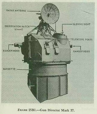
The external appearance of the director is shown in figure 25B1. The most important instruments are the two telescopes, the rangefinder, and the radar. These are essential to the primary functions of the director: measuring director train, director elevation, and present range.
The director is supported on a foundation built into the ship’s structure. This foundation is so machined as to reduce roller-path tilt to a minimum. The principal supporting elements are the base ring, the carriage, and the shield. The shield is attached to the carriage, which is supported by roller bearings on the base ring. The base ring rests on the director foundation.
The personnel (six or seven men) enter the director through the foundation and base ring, passing through hatches in the floor of the carriage. The shield has one or two observation hatches in the top. There are two telescope ports in the front plate and a vertical slot in each side plate for the protruding ends of the rangefinder. Shield thickness varies between the thin, weather-protective type for destroyers, and the heavy, splinter-proof 1 1/2-inch thick type on battleships. Telescope port covers are handwheel-operated, and on heavier shields so are the observation hatch covers. In most modifications of the director, the shield and carriage support the component parts listed below. Some of these parts are shown in figures 25B1 and 25B2:
2. Slewing sight.
3. Stereoscopic Rangefinder, 15-foot Base, Mark 42, and its carriage.
4. Change-of-range receiver.
5. Crosslevel gear and power drive.
6. Training gear with both manual and power drive.
7. Elevating gear with both manual and power drive.
8. Director train receiver-regulator.
9. Director elevation receiver-regulator.
10. Director crosslevel receiver-regulator.
11. Spot transmitter (bearing and elevation).
12. Range-spot transmitter.
13. Star-shell spot transmitter.
14. Roller-path tilt corrector (in multiple installations).
15. Horizontal-parallax mechanism (in multiple installations).
16. Radar antennas, control equipment, and indicators.
17. Target-acquisition equipment.
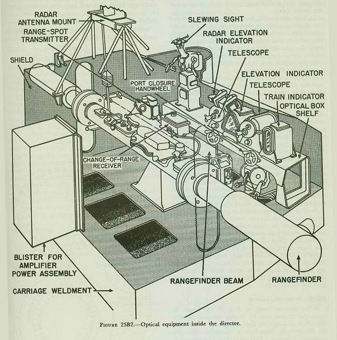
25B7. General operation
The two telescopes are mounted in housings called optical boxes. These boxes are rigidly secured to a transverse frame called the optical box shelf at the front of the director, which can be seen in figure 25B2. Within the optical box, each telescope is supported in bearings so that it can rotate about its longitudinal axis, which is paralled to the director roller path at the time of installation. The line of sight is moved in elevation by rotation of a prism within the telescope. The axis of the prism is perpendicular to the longitudinal axis of the telescope and parallel to the horizontal cross-hair. The operating principles of the telescope are illustrated in figure 25B5. The crosslevel power drive is geared to both telescopes and turns them about their longitudinal axes. The purpose of this arrangement is to keep the prism axes horizontal, so that the prisms always rotate in a vertical plane. This process is called stabilization in crosslevel.
The line of sight is kept on the target in train by turning the entire director on its roller path. The amount the director is turned from the fore-and-aft axis of the ship is a measure of director train (B’r). Elevation of the line of sight is accomplished by rotating the telescope prisms and by rotating the rangefinder about its longitudinal axis. Rotation of the radar antenna in elevation parallels rotation of the optics. The amount of rotation is the measure of director elevation (Eb).
Train and elevation of the director line of sight are controlled by mechanisms which provide for:
1. Automatic (or remote) control of the power drive, modified, as necessary, by the handwheels.
2. Local operation of the power drive by means of the handwheels.
3. Manual operation by direct gearing from the handwheels.
Train can be accomplished by one of the three means listed above, while elevation is being accomplished by the same means or by either of the remaining two.
The crosslevel drive holds the sight plane vertical. The Mark 37 director, unlike the main-battery director, has no crosslevel telescope or other means of standby operation in crosslevel.
25B8. Personnel
Each man of the director crew should be trained to handle any station, so the director can continue to function in the event of a casualty. The personnel act as lookouts through the hatches until they have a target to track.
The control officer is in charge of the entire system. He supervises the director crew, the operators of the computer and stable element, and the crews of guns controlled by his director. He designates the target to his group and, if necessary, estimates target angle (A), target horizontal speed (Sh), and rate of climb, (dH). These estimated quantities he telephones to the computer. The control officer also may make and transmit elevation and deflection spots. He issues battle orders via telephone or over an announcing system known as the 17MC, and may control the firing circuit with a portable firing key.
The rangefinder operator mans the rangefinder and can make range spots in antiaircraft fire. In surface fire he may spot in both range and deflection. Also, he may rate control in range. When the rangefinder is not used, the rangefinder operator assists the radar operator.
The radar operator controls the operation of the Radar Mark 25. He supervises the pointer and trainer in their use of the elevation and train radar scopes. He operates the radar in range, and may rate control in range. In addition, he assists the rangefinder operator when the radar is not in use.
The illumination officer, if one is assigned, acts as assistant control officer and talker for the control officer. He supervises the rear half of the director. He controls any guns firing star shells. Also, when not concerned with illumination, he is available as a relief for any station.
Sometimes a talker is stationed in the director to relay messages from other control centers to the director control officer. Because of space limitations in Mark 37 directors, this seventh station is not usually used unless there is no illumination officer available. Another possible additional station is that of a range talker, who communicates with the plotting room for the rangefinder and radar operators.
25B9. Train control
In general, operation in train and elevation are similar. Differences will be discussed in subsequent articles on elevation control.
In front of the trainer is a selector lever with which he chooses one of the three designated methods of operation, AUTOMATIC, LOCAL, or MANUAL. In manual, the trainer’s handwheels are geared directly to the training circle and he supplies the motive power. This method is slow and arduous, and is used only in the event of failure of the power drive.
In local, the gearing between the handwheels and the training circle is disengaged, and the hand-wheels are connected to the stator of a synchro in the train receiver-regulator. Through the receiver-regulator, the synchro controls an electric motor which drives the director. Thus the trainer controls the motion with the handwheels, but power is supplied by the motor.
Normally, when the target is being picked up and the problem is being set on the computer, the director is operated in local in train. When the computer starts generating a solution, it transmits bearing correction (increments cB’r) to the director. Then the trainer shifts his selector lever to AUTOMATIC. After an initial solution has been obtained, local control is used only if transmission of increments cB’r fails or if targets must be shifted.
Shifting the selector lever to AUTOMATIC leaves the handwheels connected to the synchro in the receiver-regulator, as in local. In addition, however, electrical transmission of increments cB’r from the computer is connected to the same synchro control transformer. The output of the synchro, then, is the algebraic sum of handwheel motion and increments cB’r. This sum controls the receiver-regulator, the electric motor, and thus the director’s position in train.
Bearing correction (increments cB’r) is increments of computed change in director train. It takes into account changes in train caused by relative target motion, changes in ownship’s course, and the effect of deck tilt. Deck-tilt correction is required to correct train errors introduced by roll and pitch. If increments cB’r is correct the line of sight stays on the target without handwheel motion. However, if the bearing correction input is in error, it is the duty of the trainer to bring the line of sight back on target with the handwheels.
25B10. Train rate control
If the director tends to drift off the target in train, the trainer can, by closing the rate control key while he keeps the line of sight on target with his handwheels, introduce a correction into the computer solution. This procedure is necessary if one of the quantities A, Sh, or dH is in error, or if there is a change in target course or speed. If the target becomes obscured, the trainer allows increments cB’r to continue to drive the director and sends no rate control signal until the target reappears.
Rate controlling can also be accomplished by the computer operators. The director trainer holds his key closed when on target as in automatic rate control; however, his key actuates a signal at the computer which indicates only that he is on target.
25B11 Slewing the director
When the director is power driven (local or automatic), the control officer may slew the director intrain and elevation. He closes a key on the grip and points the slewing sight (illustrated in figure 25B2) at the target. By this procedure, control of the director is taken away from the pointer and trainer, and the director is driven at high speed until its line of sight coincides with that of the slewing sight. The control officer uses this sight to bring a target into the fields of the optics, and thus designates the target to the director crew.
25B12. Train and elevation indicators
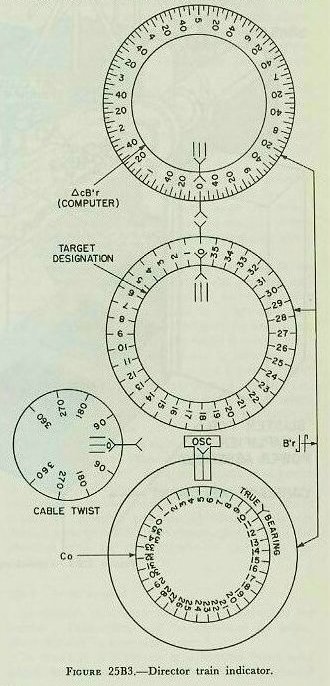
The train indicator is located on the optical shelf to the right of the trainer’s telescope. It receives increments cB’r electrically from the computer, and director train (B’r) mechanically from the director. It has four dial groups arranged as shown in figure 25B3.
The upper group consists of an inner dial and a ring dial. The inner dial has only a pointer and is driven by increments cB’r from the computer in such a way that one revolution of this dial is equal to 10° of increments cB’r. The ring dial is driven by director train, with one revolution of the dial representing 10° of B’r. With the director in local or manual, the trainer can follow the solution by matching the ring dial against the inner dial. If these two dials rotate together, the director is training at the same speed as the computed value. Such procedure would be followed if the target is obscured visually or is lost by the radar
The center group also consists of an inner dial and a ring dial. The ring dial shows actual director train with one revolution equal to 360° of B’r. This dial is graduated in 10° increments and is used in conjunction with the ring dial of the upper group. The inner dial has only a pointer, which is driven by a signal from some unit outside the director for target designation. The trainer picks up a designated target by matching the ring dial against the inner dial.
The bottom group has an inner dial and a ring dial. The ring dial is driven by director train, with one revolution equal to 360° of B’r. It has only a single pointer. The inner dial is driven by own-ship course (Co) from zero to 360 degrees. This dial is graduated in 10° increments. By reading the ring pointer against the inner dial, true director bearing a determined. This is useful for locating a target whose true bearing has been supplied by an external source.
At the edge of the indicator face, halfway between the center and bottom groups, is a small dial for reading cable twist. The purpose of this dial is to show how far the director has trained in either direction from its neutral position. In order to protect its connecting cables from excessive twist, the director is limited to 375° of train in either direction from neutral. The dial shows how much farther the director can be trained before the limit stops are reached.
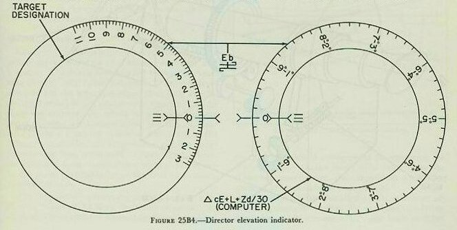
The left dial group has an inner dial and a ring dial. The ring dial is driven by Eb and is graduated in 2° increments from minus 30° to plus 110°. The inner dial has only a pointer, which is driven by some external unit for target designation.
The right-hand dial group also has an inner dial and a ring dial. The ring dial is driven by director elevation, with one revolution equal to 10° of Eb. The inner dial has only a pointer driven by elevation correction (increments cE+ L+Zd/30) from the computer. In local or manual, the pointer can match these two dials and thus follow the computer solution, should he lose the target temporarily.
25B13. Elevation
As explained before, the description of director train in article 25B9 is generally true of director elevation. The telescope prisms rotate; the range-finder rotates about it longitudinal axis; and the radar antenna rotates about its mounting as the pointer follows the target in elevation. In manual the pointer’s handwheels are geared directly to the prisms, the rangefinder elevating arc, and the radar antenna elevating gearing. In local or automatic, the electric motor of the power drive is connected and the handwheel connection broken. Then the handwheels are connected to a synchro control transformer in the elevation receiver-regulator. In automatic, elevation is controlled by the algebraic sum of handwheel motion and elevation correction (increments cE+L+Zd/30).
It can be seen from figure 25A1 that director elevation (Eb) is the sum of target elevation and level angle. (Eb=E+L.) To hold the line of sight on the target automatically, changes in elevation due to relative target motion must be supplied. These changes are supplied in the form of increments of generated elevation (increments cE). It can be seen that, to hold the line of sight steady, changes in level must be supplied. Therefore, continuous values of L are received from the stable element via the computer. L, then, is the second element of elevation correction. Since continuous values of level are received (in automatic) the sights, rangefinder, and radar are said to be stabilized in level. In local or manual, the director is not receiving signals from the computer, and therefore automatic stabilization in level is not possible. Elevation correction is supplied by the pointer’s handwheels as he turns them to stay on the target. The elevation operator normally stays in automatic when picking up or shifting targets, so as not to lose the advantage of the level input.
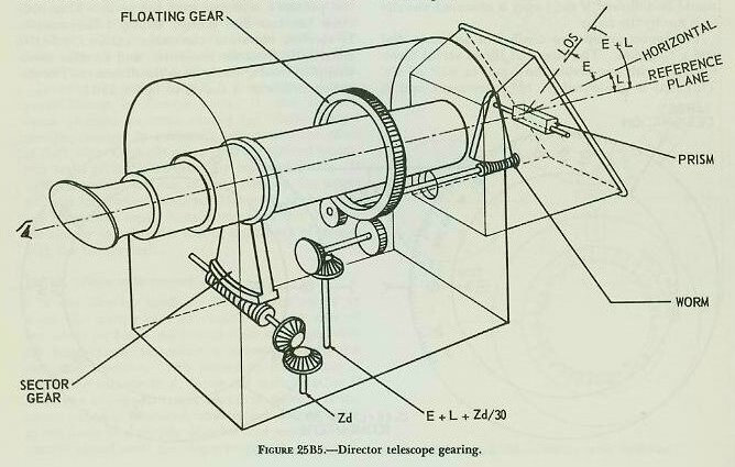
The third element of elevation correction, Zd/3O, is called crosslevel function. Its purpose is to counteract an error caused by the telescope gearing. Figure 25B5 shows the operating principle of the telescopes. Prisms rotation is caused by the input gear driven by the elevation drive. Control of the elevation drive has already been described. The input gear turns the floating gear, which is free to rotate and which acts as a spur gear. This floating gear drives another gear at the end of the worm shaft, turning the worm, which in turn elevates or depresses the prism.
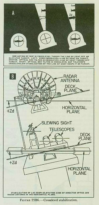
When the telescope is stabilized in crosslevel (figure 25B6), Zd drives an input gear which drives the sector gear. Movement of the sector gear causes the telescope to rotate about its longitudinal axis, keeping the prism axis horizontal. However, the worm and its shaft move with the prism. This causes the gear at the end of the worm shaft to walk around the floating gear. Since the floating gear is meshed with the elevation-drive input gear, it cannot be rotated by the worm gear. Thus, the worm gear turns as it walks around the floating gear, introducing an undesired movement of the prism in elevation. Because of the gear ratio used, the error introduced is equal to Zd/3O. To counteract the error, Zd/30 is introduced through the elevation input gear, and rotates the floating gear to eliminate the error as fast as crosslevel stabilization introduces it. Zd/30 does not exist as a separate quantity. The stable element generates the combined quantity L+Zd/30, which is sent to the computer. In the computer, increments cE is added to form elevation correction increments cE+ L+Zd/30.
25B15. Crosslevel
Crosslevel stabilization is accomplished by a power drive, consisting of a receiver-regulator and a motor. The motor is connected to the telescopes, rangefinder, and radar antenna. The crosslevel drive rotates the telescopes about their long axes by an angle equal to Zd, as shown in figure 25B6. In a similar manner, the whole rangefinder and the radar antenna are rotated about the line of sight by Zd. As a result of crosslevel stabilization, the telescope crosshairs, the rangefinder, and the radar antenna are kept horizontal. Consequently, director elevation is measured in the vertical plane, not in the plane perpendicular to the deck as in main-battery directors.
The crosslevel receiver-regulator receives continuous values of Zd from the stable element. No method is provided for manual inputs of crosslevel except for a manual arrangement for returning the drive to zero. In the event of a casualty to the crosslevel power drive, the rangefinder and radar antenna are locked at zero crosslevel.
Limit switches are installed in the crosslevel receiver-regulator to protect the equipment. When the value of Zd reaches 17˝°, the limit switches operate to stop the motor. When the value of Zd returns to less than 17˝°, the motor cuts in again.

On the rangefinder beam in front of the range-finder is a change-of-range receiver, shown in figure 25B7. It contains only a synchro receiver and a servo. Increments of generated range (increments cR), called range correction, are received by the synchro from the computer. The servo drives the increments cR signal into a differential in the rangefinder, where it is combined with motion of the rangefinder operator’s hand knob to produce an output which positions the rangefinder’s measuring wedges. In addition, the differential output positions synchro-transmitter rotors which transmit observed present range (R) to the computer.
The rangefinder operator uses his knob to bring the wander marks above the target. Then, if the computer solution is correct, increments cR will keep the wander marks on the target, and the operator merely observes. If the solution is incorrect, the wander marks will drift away from the target, whereupon the operator turns his knob to bring the marks back on target. If either the change-of-range receiver or the increments cR transmission fails, the operator must do the entire job of keeping the measuring wedges properly positioned. If the transmission of R fails, he must send the values of R to Plot by phone, to be set into the computer by hand.
In the center of the range knob is a button known as the rate control signal button. It is used in the same way as the rate control keys on the pointer’s and trainer’s handwheels. If the computer is set for automatic range rate control, the operator can rate control in range by pressing the button as he turns his knob. If rate controlling in range is done at the computer, pressing the button tells the computer operators that a correct value of R is being transmitted.
25B17. Spotting
On the rangefinder beam in front of the rangefinder and to the left of the change-of-range receiver is a range-spot transmitter. This transmitter sends both individual and total spot values to the control officer’s spot transmitter, but sends only the total value of range spot to the computer. The instrument has one dial group, consisting of an inner dial and a ring dial. The ring dial indicates the value of each individual spot. This dial and its synchro are so geared that, when the spot knob is pushed in, the dial returns to zero. The inner dial shows the value of total range spot transmitted. The knob has 50-yard detents, so the operator can make spots by touch.
To the left of the control officer’s station is a spot transmitter. It has three dial groups arranged vertically, each with an inner dial and a ring dial. All three groups show the value of individual spots on the ring dial and the total spot on the inner dial. From top to bottom they show range, elevation, and deflection spots in that order. The top or range group merely repeats what is on the range-finder operator’s range-spot knob on the control officer’s spot transmitter, since range spots are transmitted by the rangefinder operator’s transmitter. The elevation and deflection dial groups, used by the control officer in spotting, each have a spot knob that functions the same way as the range-spot knob or the range-spot transmitter. These two knobs have 1-mu detents so the control officer can spot by touch. Only total values of elevation and deflection spots are transmitted to the computer by this instrument.
25B18. Illumination control
Star-shell fire is controlled by a star-shell computer attached to the Mark 1A computer. Star-shell gun train, elevation, and fuze-setting orders are calculated by the star-shell computer and transmitted only to the guns firing star shells. Located at the illumination control officer’s station in the director is a star-shell spot transmitter. It functions in the same way as the control officer’s spot transmitter, except that the spots are star-shell range, elevation, and deflection spots. It has a range-spot knob as well as elevation-spot and deflection-spot knobs.
25B19. Multiple installations
On ships with only one director, the director roller path is the reference plane, and its axis of rotation determines the reference point in train. When more than one director is installed, all must transmit identical values of director train and director elevation for the same reference point. To this, each director has a roller-path tilt corrector and a horizontal-parallax corrector.
The parallax corrector is in the train receiver-regulator. It receives unit parallax calculated in the computer for a 100-yard horizontal base length. In the receiver-regulator, the electrical signal from the computer is transformed to mechanical movement by a follow-up. Then a signal gear ratio converts unit parallax to the correct amount for the director’s actual distance from the reference point. This corrected parallax is fed to a mechanical differential. The other side of the differential receives actual director train. The output is director train corrected for horizontal parallax, which is the value of B’r that would be transmitted by a director actually at the reference point. B’r then is sent to the director train indicator and to the computer.
Should parallax transmission or the follow-up fail, manual application of parallax is possible. Two concentric parallax dials are located in the face of the train receiver-regulator. The ring dial is graduated for unit parallax, and is driven by the follow-up mechanism. The inner dial has only a pointer and is driven by the parallax synchro receiver. When the follow-up mechanism fails, a hand crank is used to match the zero on the ring dial against the pointer on the inner dial. This causes the correct parallax to be introduced. If parallax transmission fails, unit parallax can be received by phone and set on the outer dial against a fixed index. In either of these two cases, the crank performs the functions of the follow-up.
The roller-path tilt corrector is located on the director carriage. Inclination of the director roller path from the reference plane is corrected in accordance with alignment data determined as described in chapter 21. Roller-path inclination in the sight plane is a function of the angle of director train from the high point. Director train B’r is a mechanical input to the tilt corrector. The train value of the high point and the inclination of that point are set on the mechanism after alignment has been checked. The output of the corrector is combined with director elevation above the roller path. The result is director elevation above the reference plane (Eb).
25B20. Radar
The Mark 25 radar is an automatic tracking fire control radar. Its antenna and parabolic reflector are mounted atop the director. Indicator scopes and other associated components are located in the director and below decks. This radar provides for three types of antenna scan: spiral for target acquisition, conical for tracking, and circle for spotting shell splashes in surface fire.
In normal operation, the automatic tracking feature relieves director personnel of making rate control corrections. Tracking signals-representing target range, bearing, and elevation-are generated from the radar information and compared with the generated range, bearing, and elevation from the computer. Any differences between the computer and radar quantities are transmitted to the director as corrections, to reposition it in accordance with the radar information.
The corrections, in turn, are transmitted to the computer, where they correct its solution until it matches the radar values. Once the target has been acquired by the radar, this process is continuous and automatic.
Characteristics of the Mark 25 radar are described in volume 3 of this course.