
INDEX Back to Main Fire Control Page
A. Fire Control Problem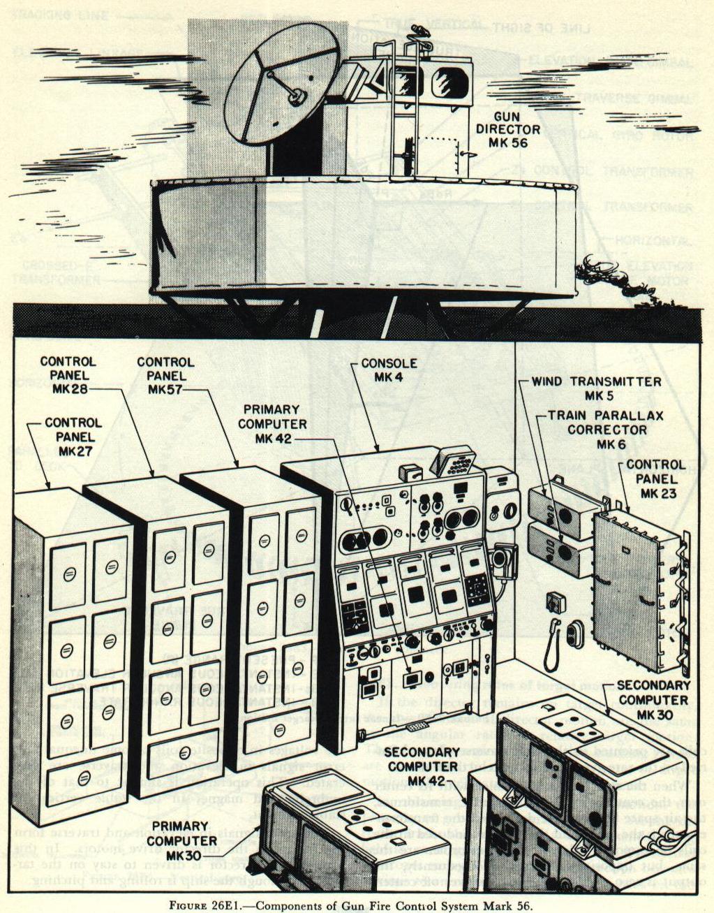 Gun Fire Control System Mark 56, illustrated in figure 26E1, is an intermediate-range antiaircraft fire control system. Designed for use against high-speed subsonic aircraft targets, it provides gun train, gun elevation, and fuze orders for 3-, 5- and 6-inch guns. It may also be used against surface targets. Where a ship has two batteries (of different calibers) capable of AA fire, the system can produce different gun orders for both batteries simultaneously, thus permitting both to fire on the same target. This variation is known as a dual-ballistic system.
The system incorporates:
1. Automatic radar tracking in bearing, elevation, and range, as accurate as the best optical tracking.
Gun Fire Control System Mark 56, illustrated in figure 26E1, is an intermediate-range antiaircraft fire control system. Designed for use against high-speed subsonic aircraft targets, it provides gun train, gun elevation, and fuze orders for 3-, 5- and 6-inch guns. It may also be used against surface targets. Where a ship has two batteries (of different calibers) capable of AA fire, the system can produce different gun orders for both batteries simultaneously, thus permitting both to fire on the same target. This variation is known as a dual-ballistic system.
The system incorporates:
1. Automatic radar tracking in bearing, elevation, and range, as accurate as the best optical tracking. 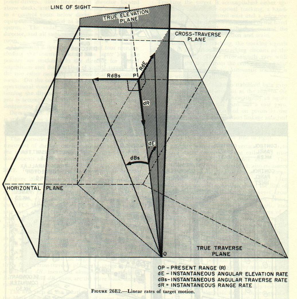 Figure 26E2 shows some of the space relations used in the Mark 56 system. The angular velocity of the LOS can be resolved into angular rates in two planes, elevation and traverse, dE and dBs. In the GFCS Mark 56, these rates are measured by the rate gyro, which is stabilized and hence measures the rates in the true elevation and the true traverse plane.
The solution, however, requires the use of linear rates of target motion, in a plane perpendicular to the line of sight at target’s position. This plane is called the cross-traverse plane, and contains RdE and RdBs. Since the target is not moving entirely in the cross-traverse plane, the range changes at the rate dR, measured along the line of sight. RdE, RdBs, and dR, then, are the three basic linear rates of target motion.
The first step in the solution of the problem by the Mark 56 is the determination of target position. Target bearing and elevation are measured by the director. As the target is tracked, director train, B’r’ and director elevation E’b are measured and transmitted by the synchros; electrical signals representing these angles are transmitted continuously to the computer. Target range (R) is measured by gating the target pip on the radar indicator. The range signal is transmitted automatically from the radar equipment to the computer.
Tracking the target is accomplished either optically or by radar. For optical tracking, a handgrip type of tracking control unit and a telescope are provided on the director. Rotation of the hand grips generates electrical signals that control the director power drives in elevation and train.
In automatic radar tracking, the tracking signals originate in the automatic tracking circuits of the radar equipment. These error signals vary with deviation of the target from the (enter of the radar beam when in conical scan. Automatic tracking is accurate within one-half mile.
Figure 26E2 shows some of the space relations used in the Mark 56 system. The angular velocity of the LOS can be resolved into angular rates in two planes, elevation and traverse, dE and dBs. In the GFCS Mark 56, these rates are measured by the rate gyro, which is stabilized and hence measures the rates in the true elevation and the true traverse plane.
The solution, however, requires the use of linear rates of target motion, in a plane perpendicular to the line of sight at target’s position. This plane is called the cross-traverse plane, and contains RdE and RdBs. Since the target is not moving entirely in the cross-traverse plane, the range changes at the rate dR, measured along the line of sight. RdE, RdBs, and dR, then, are the three basic linear rates of target motion.
The first step in the solution of the problem by the Mark 56 is the determination of target position. Target bearing and elevation are measured by the director. As the target is tracked, director train, B’r’ and director elevation E’b are measured and transmitted by the synchros; electrical signals representing these angles are transmitted continuously to the computer. Target range (R) is measured by gating the target pip on the radar indicator. The range signal is transmitted automatically from the radar equipment to the computer.
Tracking the target is accomplished either optically or by radar. For optical tracking, a handgrip type of tracking control unit and a telescope are provided on the director. Rotation of the hand grips generates electrical signals that control the director power drives in elevation and train.
In automatic radar tracking, the tracking signals originate in the automatic tracking circuits of the radar equipment. These error signals vary with deviation of the target from the (enter of the radar beam when in conical scan. Automatic tracking is accurate within one-half mile.
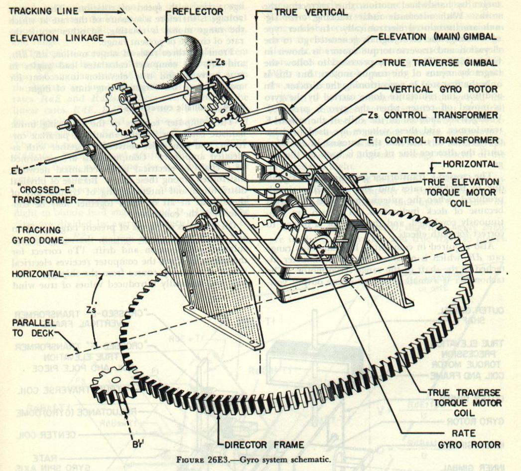 The director line of sights is stabilized by a gyro unit, located in a compartment at the rear of the director. The unit, shown schematically in figure 26E3, consists of a vertical gyro and a rate gyro. The gyroscope unit is mounted on pivots in the gyro compartment. The elevation linkage attached to the antenna elevating gear is used to tilt the gyro main (elevation) gimbal so as to maintain the gyro gimbal axes parallel to the line of sight.
The primary purpose of the vertical gyro is to
The director line of sights is stabilized by a gyro unit, located in a compartment at the rear of the director. The unit, shown schematically in figure 26E3, consists of a vertical gyro and a rate gyro. The gyroscope unit is mounted on pivots in the gyro compartment. The elevation linkage attached to the antenna elevating gear is used to tilt the gyro main (elevation) gimbal so as to maintain the gyro gimbal axes parallel to the line of sight.
The primary purpose of the vertical gyro is to
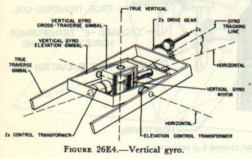 establish a stable reference plane called the true traverse plane, as shown in figure 26E2. The vertical gyro, as shown in figure 26E4, also measures E, true elevation of the director line of sight above the horizontal, and Zs, cross-traverse angle. Like cross level, cross traverse is motion about the line of sight due to movement of the deck. However, cross traverse is measured in the cross-traverse plane, which is perpendicular to the line of sight, and therefore differs from cross level. The values of E and Zs are picked off by elevation and cross-traverse control transformers and are transmitted to the computer, where they are applied in calculating ballistic corrections and gun orders. Zs also goes to the cross-traverse drive gear of the rate gyro.
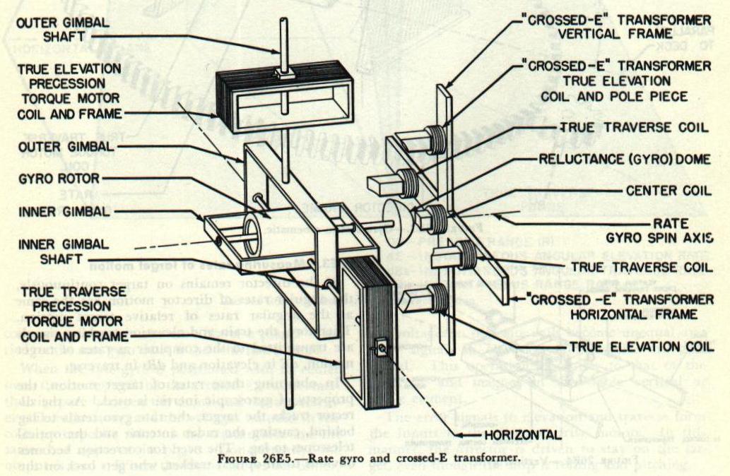 The rate gyro, shown in figure 26E5, controls the drive motors which position the director in train and elevation. The gyro does this by measuring the angular rates of target motion in the form of electrical tracking signals and combining these signals with the stabilizing signals generated as a result o deck motion. The algebraic sum of these signals is obtained in a set of pick-off coils called a crossed-E transformer and shown in figure 26E5. The crossed-E transformer is composed of five coils arranged to form a cross with axes at right angles. The center coil is energized by 100 volts, alternating current. This voltage induces voltages in the other coils. Supported by the vertical frame, coils are kept oriented in the vertical plane through the tracking line, as shown in figure 26E3, and are connected in phase opposition. The other two coils are oriented in the true traverse plane. Carried on the rate gyro shaft is the reluctance dome.
A. Fire Control Problem
B. Basic elements of lead-computing sights
C. Gun sight Mark 15
D. Gun Fire Control System Mark 63
E. Gun Fire Control System Mark 56, Page 1 (This page)
E. Gun Fire Control System Mark 56, Page 2
E. Gun Fire Control System Mark 56, Page 3
E. Gun Fire Control System Mark 56, Page 4
E. Gun Fire Control System Mark 56, Page 5