NAVAL ORDNANCE AND GUNNERY
VOLUME 2, FIRE CONTROL

Relative-Rate Antiaircraft Systems
Chapter 26D Gun Fire Control System Mark 63


INDEX Back to Main Fire Control Page

A. Fire Control Problem Chapter 26B

B. Basic elements of lead-computing sights

C. Gun sight Mark 15

D. Gun Fire Control System Mark 63 Chapter 26D  (This page)

E. Gun Fire Control System Mark 56 Chapter 26E

D. Gun Fire Control System Mark 63


26D1. General description

Gun Fire Control System Mark 63 is manually operated and is designed to control the fire of 40mm and 30”/50 guns against air targets at ranges from 800 to 7,000 yards.

Range rate limits on later installations are plus 350 knots and minus 800 knots.

Targets may be tracked either optically or by radar.

The radar antenna is carried on the gun mount.

The system uses a disturbed line of sight, meaning that while the sight housing and gun barrels are aimed at future target position, the optical line of sight and radar beam remain on the present target position. See Figure 26D2. 26D-2 
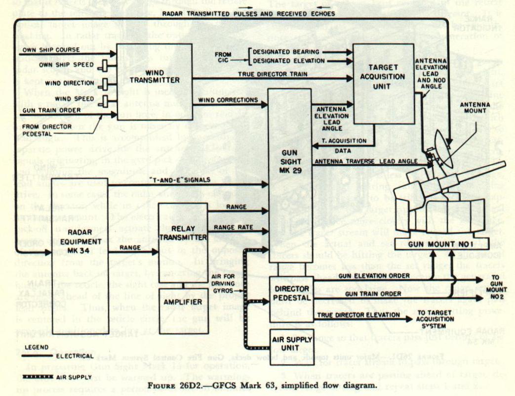
The major units included in the system are:

1. Gun sight Mark 15 or Mark 29.
2. Director pedestal.
3. Antenna mount.
4. Radar equipment.
5. Wind transmitter.
6. Target acquisition unit (TACU).
7. Train parallax corrector (if guns are displaced sufficiently far from the director to require parallax correction).

26D2. Operation

A crew of six is required for operation.

Topside personnel are the control officer, the director pointer, the director range setter, and the gun control talker.

The target acquisition unit (TACU) operator and the radar operator are stationed below decks.

A Lead-Computing Sight Mark 15 or Mark 29, employing air-driven gyroscopic computing mechanisms, is mounted on a pedestal-type director.

The director is swung manually by the director pointer in train and elevation.

Tracking can be accomplished in two ways.

If the target is visible, it is tracked by keeping the reflection of the target image centered on a fixed reticle in the optical telescope. This method is known as optical tracking.

If the target is obscured, or in case of night firing, the director pointer tracks a radar target spot which is introduced into the optical line of sight by a train and elevation scope in the gun sight. This method is called blind tracking.

When the target is sighted optically, the director pointer slews the director to get on, using an auxiliary telescope.

A caging switch on the left handle of the director is pressed during this operation to prevent the gyros from generating a large false lead angle.

As quickly as possible after the target is picked up in the auxiliary telescope, the pointer shifts to the tracking telescope of the gun sight and starts tracking smoothly, releasing the caging switch as the target is tracked.

Corrective data from other units in the system (wind transmitter for wind corrections and radar for ranges and range rates) are transmitted to the director and applied as inputs to the gun sight automatically or by the range setter, who matches zero readers, thus sending these corrections into the gun sight.

The corrections cause movement of the mirrors in the gun sight, changing the relative positions of the target image and reticle.

The pointer, in maintaining the center of the reticle on the target, causes the director and the guns it controls to be offset from the line of sight and to point ahead of (lead) the target, because of movement of the mirrors in the optical system caused by precession of the gyros.

The lead angle compensates for the relative motion of the target and for the effects of gravity, wind, drift, and spots, if any.

The lead angle is composed of two components: One in elevation, the other in train.

The latter is corrected for horizontal parallax before being used at the gun, in installations where this refinement is warranted.

The amount the director is offset from the LOS in elevation and train is continuously sent to the gun during tracking in the form of signals which control power drives at the gun.


26D3. Improved modifications

In later modifications of the Mark 68 system, the Mark 29 sight has replaced the Mark 15 sight, as it provides for handling greater target speeds.

Also the Mark I Mod 0 director pedestal has replaced the Mark 51 director in later installations.

The Mark 1 Mod 0 director pedestal incorporates one important feature not installed on the Mark 51 director, a cross-roll gyro.

When the computer “cross rolls” or swings about the line of sight because of deck inclination, the elevation and train gyros tend to exchange functions.

This exchange, however, is retarded somewhat by gyro damping.

To compensate for errors caused by the damping, the cross-roll gyro measures cross roll directly and modifies the output of the sight accordingly by means of cross-roll torque motors on the gyro output shafts in the Mark 29 sight.

26D4. Radar equipment

The earliest Mark 63 systems used Radar Equipment Mark 28, while all others use the Mark 34, which will be described.

The Mark 34 radar sends to the gun sight values of range and range rate which are used in computing lead angles both in full and in partial radar control, in addition, the radar provides target-position signals for blind tracking.

In blind tracking, as in optical tracking, the director is positioned manually, but the radar equipment aids the director pointer by locating an obscured target initially by means of the TACU unit, and providing a target indication in the sight as a spot in the scope which can then be tracked, once the radar beam has been placed on the target.

As shown in figures 26D1 and 26D3, the radar antenna is mounted in a gimbal above the gun trunnions on the mount. 26D-1 26D-3 
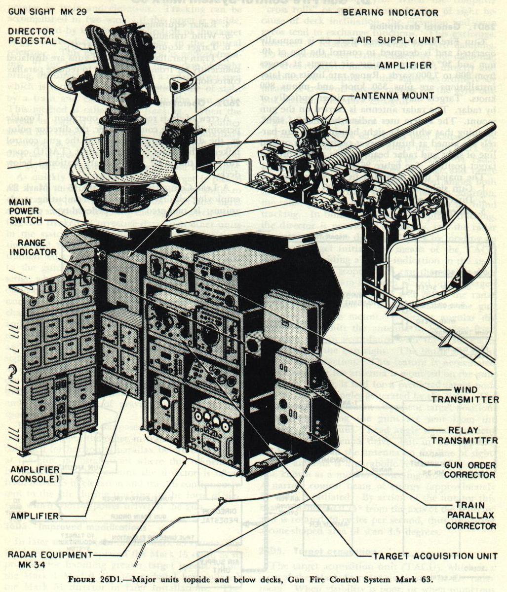
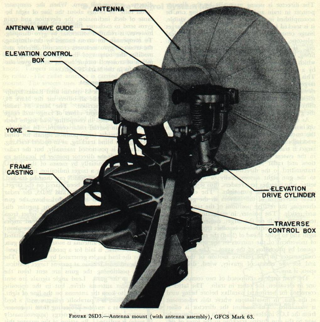
Sufficient angular displacement permits the antenna to be offset from the bore axis in accordance with the lead angles generated by the gun sight.

The limits are about 30° in any direction.

This feature is necessitated by the fact that the antenna is mounted on the gun, which, of course, is laid for a predicted target position by the lead angles generated by the sight.

The radar beam must remain at present target position.
Signals positioning the guns are sent from the director to the guns.

Lead angle signals are sent to the radar antenna drive, but in the opposite direction, to keep the antenna on the line of sight.

The antenna is a parabolic reflector with a feed line known as a nutator projecting from its center.

A narrow conical beam of energy (approximately 3° wide) is radiated.

By action of the nutator this beam is deflected 0.75° from the axis of the reflector
and is rotated 30 cycles per second, thus providing a cone-shaped area of scan 4.5 degrees.

26D5. Target acquisition

The target acquisition unit (TACU), which is a part of the Mark 34 radar, is located in the radar room.

When visibility is poor, or when numerous targets are at the same approximate location, the TACU aids the director operator in acquiring the designated target.

The TACU operator receives target information from an outside station, such as a search radar or a lookout, and can control the position of the TACU spot in the director pointer’s train and elevation (T&E) scope to indicate the direction of movement necessary to point toward the designated target.

If the target fails to appear in the TACU scope, the TACU operator can cause the antenna to nod in elevation at an angle of either ±15° or ±5° by a selector switch.

Search in bearing can also be accomplished by throwing a switch which causes the spot to move back and forth in the T&E-scope.

If the director pointer follows the spot, the TACU operator is enabled to scan a small bearing sector about the designated bearing.

Close cooperation between TACU operator and director pointer is necessary to locate and get on a designated target.

It should be noted that the spot used to coach the director pointer on the target is controlled by the TACU operator and is not the spot which appears on the pointer’s scope once the target lies within the radar beam.

Once the target has been picked up by radar, the TACU operator can determine range, bearing, and elevation data from a scope of the TACU.

26D6. Ranging

The radar operator, also stationed in the radar room, has two units which provide visual information about the target; namely, the control indicator and the range unit.
On the control indicator, echoes from targets within the radar beam appear as pips along the horizontal sweep.

The range-measuring indication is a sharp drop or step in the sweep line.

When the step is set adjacent to the leading edge of a pip, a counter on the range unit shows the range in yards.

By throwing a selector switch, a choice of three sweeps is possible as shown in figure 26D4. 26D-4 
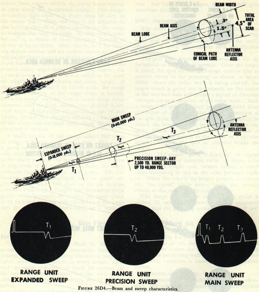
Main sweep, used for locating distant surface and air targets, shows all targets within the beam from 0 to 60,000 yards.

The range crank moves the step to a maximum of 40,000 yards, beyond which target range must be estimated.

Expanded sweep is accurate and is sufficient for most air targets, since it includes the firing range.

It shows all targets from 0 to 18,000 yards, the range step again moving as the range crank is turned.

Precision sweep, used for very accurate range measurement and tracking, covers any desired 2,500-yard sector of the entire measurable range (40,000 yards).

In this case the step remains in the center of the sweep and the pips move along the trace as the crank is turned.

A small portion of the sweep, (about 300 yards in range), is known as the range gate.

The target is gated by turning the range crank on the range unit until the leading edge of the pip is adjacent to the sharp point at the base of the step.

A drop in amplitude of all pips and grass along the sweep indicates that a target has been gated.

Effective tracking can be accomplished only on gated targets, since no others will show up on the director pointer’s T&E-scope.

Targets may be tracked (kept gated) either manually by moving the range crank or by an aided tracking unit which causes the range step to move along automatically at a uniform rate.

For fast-moving targets, the latter will give smoother tracking.

26D7. Operation in train and elevation

The scope on the control unit duplicates the image on the director pointer’s T&E-scope.

This train and elevation indicator permits the radar operator to work more closely with the director pointer.

The gun sight contains a T&E-scope for the information of the director pointer.

Once the target is gated, the spot on the T&E-scope enables him to correct errors in the pointing, as shown in figure 26D5. 26D-5 
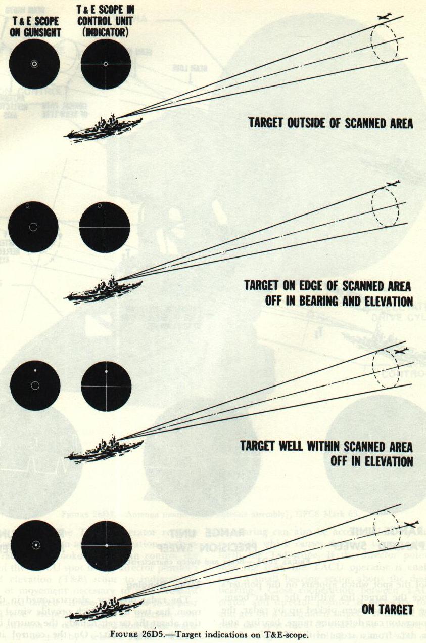
Since the radar beam is being rotated, the target which is gated but not exactly on the center of the antenna axis will return a signal of different strength for each position of the radar beam.

Such a target will give an image (spot) displaced from the center of the T&E-scope, and the direction of the spot from the center indicates the direction in which the antenna must be moved to center the spot.

When the target is exactly on the axis of the antenna, the spot is in the center of a circular reticle.

Keeping the spot so centered tracks the target.

The T&E-scopes give indications of signal strength as well as pointing error.

A strong echo appears as a bright spot, weaker echoes as small rings increasing in size as the echo becomes weaker.

When the echo is no longer present, a concentric “no signal” circle settles inside the circular reticle at the center of the scope.

The range accuracy of the Mark 34 radar is within 15 yards ±0.1 percent of the measured range, and the pointing accuracy is within 1 mil. Bottom of Gun Fire Control System Mark 63 Page

A. Fire Control Problem
B. Basic elements of lead-computing sights
C. Gun sight Mark 15

D. Gun Fire Control System Mark 63
E. Gun Fire Control System Mark 56, Page 1
E. Gun Fire Control System Mark 56, Page 2
E. Gun Fire Control System Mark 56, Page 3
E. Gun Fire Control System Mark 56, Page 4
E. Gun Fire Control System Mark 56, Page 5

Index: Main Fire Control Page